For each video pipe of the DIVO option board, the General Purpose Interface (GPI) provides two channels of input and output trigger signal pairs. This appendix explains
“GPI Receiver, Switch Closure Mode, and Current Sense Mode”

Note: This appendix is pertinent to the DIVO option board only; the information in it does not apply to the DIVO-DVC option board.
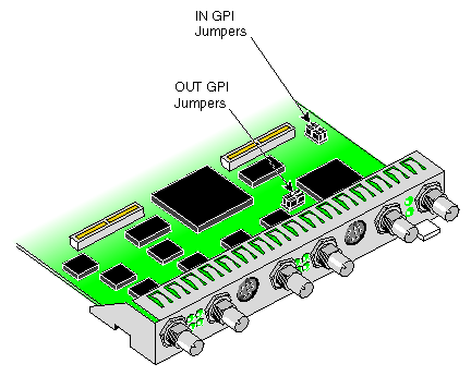
The DIVO board has two GPI headers. Each GPI header (row of four pins) configures one of four receiver channels: two channels for GPI in and two channels for GPI out. Figure G-1 shows the location of the jumper pins on the DIVO option board.
| Note: This information on GPI jumpers pertains to the DIVO option board only; it does not apply to the DIVO-DVC option board. |
Note that the jumpers for the OUT GPI connector are near the OUT GPI mini-DIN connector, while the jumpers for the IN GPI connector are relatively far away from the IN GPI connector.
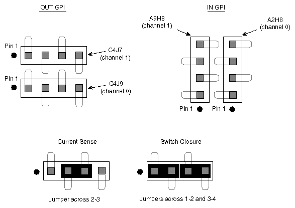
For the factory setting of switch closure mode, two jumpers are factory-installed, shorting pins 1-2 and pins 3-4. These jumpers need not be moved unless you wish to use current sense mode. You can choose to mix the modes for the various channels. This reconfiguration is typically performed by a SGI System Service Engineer when the DIVO board is installed in the chassis. Switch closure and current sense modes are explained in “GPI Receiver, Switch Closure Mode, and Current Sense Mode”.
Figure G-2 shows GPI headers and jumpering. The printed circuit board (PCB) reference designators are included to aid identification of the header associated with each GPI receiver channel.
| Note: This information on GPI jumpers pertains to the DIVO option board only; it does not apply to the DIVO-DVC option board. |
For information on VL controls for configuring the GPI ports, see “VL Support for the General-Purpose Interface ( GPI)” in Chapter 2. For information on the GPI connectors and transmitter, see “GPI Interface” in Appendix A.
GPI contact closure receive (CCR) inputs use an optical isolator device to provide a means of electrical isolation from source equipment. The device consists of a bidirectional input LED optically coupled to a bipolar transistor. A voltage pulse applied across the CCR+/- pins causes the LED to become forward-biased and to produce a GPI trigger to the computer.
Table G-1 summarizes electrical specifications for the GPI receiver optoisolator.
Table G-1. GPI Receiver Input Optoisolator
Parameter | Value |
|---|---|
Forward voltage (VF) | 1.55 V, 1.2 V typical (IF = 10 mA) |
Continuous forward current (IF) | 30 mA |
Peak forward current | 1000 mA (10 us duration, 1% DC) |
Reverse current (IR) | 0.1 uA, 100 uA maximum (VR = 6 V) |
Isolation surge voltage (V10) | 2500 VACRMS (t = 1 min) |
Depending on jumpering (see “GPI Headers (DIVO Option Board Only)”), the DIVO board GPI receiver can be set to switch closure or current sense mode, as discussed in these sections:
“GPI Receiver Current Sense Mode (DIVO Option Board Only)”

Note: Setting the board for current sense mode is possible only for the DIVO option board, and only at the time of installation. Current sense mode does not apply to the DIVO-DVC option board.
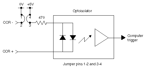
Figure G-3 shows switch closure jumpering, which creates a digital pulse.
In switch closure mode, the +5 V power supply and ground of the DIVO board are not electrically isolated from the chassis of the source equipment.
For switch closure mode, the GPI receiver can be interfaced to the source equipment by tying the CCR+ and CCR- terminals across the output terminals of an optoisolator, solid-state relay, or any device that acts like a single-pole contact switch. A GPI trigger is generated as long as the source switch is closed.
| Note: Polarity of the CCR+/- signals must be observed for the source equipment in switch closure mode. |
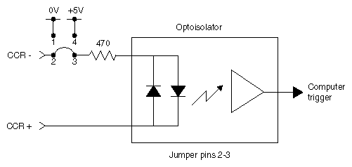
Figure G-4 shows current sense jumpering.
| Note: Setting the board for current sense mode is possible only for the DIVO option board, and only at the time of installation. Current sense mode does not apply to the DIVO-DVC option board. |
In current sense mode, the DIVO board is electrically isolated from the chassis of the source equipment.
For current sense mode, the CCR+ and CCR- signals can be interfaced by tying the CCR+ terminal to the output of a TTL or CMOS logic device, and by tying the CCR- terminal to GND of the source equipment. Whenever the logic device is sourcing current (driving a logic high), a GPI trigger is generated.
In current sense mode, the logic sense can be swapped (inverted) by moving the CCR- signal from GND to the logic power supply (typically VCC) of the source equipment. The CCR+ signal remains connected to the output of the logic device; however, in this configuration an open collector type device can be used. Whenever the logic device is sinking current (driving a logic low), a GPI trigger is generated.


