This chapter discusses the controls and connectors of the Vault and
SCSIBox 2.
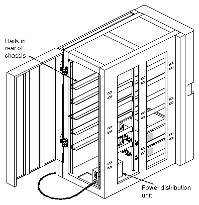
Figure 2-1 shows the major components of the Vault.
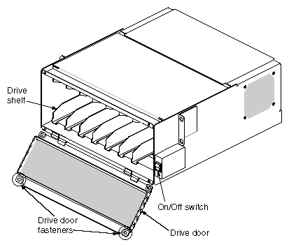
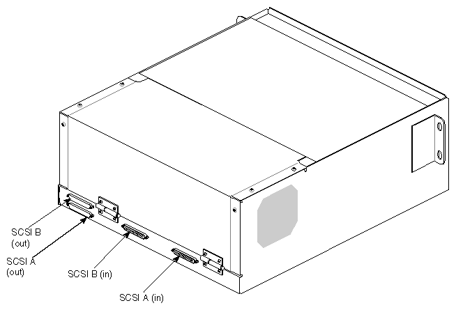
This section describes the front and rear components of the SCSIBox 2. Figure 2-2 and Figure 2-3 show the major components of the box.
These components are located on the front of the SCSIBox 2 (see
Figure 2-2):
| Drive door | opens and closes using two quarter-turn, wing-nut fasteners near the top corners of the box. Be careful not to overturn the fasteners or else they may break off. |
| Caution: The door must be in place during operation to comply with FCC regulations and for proper air flow. |
| On/Off switch | controls power to all the drives. | |
| Drive shelves | house the SCSI drives and drive sleds. The shelves are removable to accommodate full-height drives. |
| Note: Each full-height drive occupies two half-height slots. |
These major components are located on the back of the SCSIBox 2 (see Figure 2-3):
| SCSI In (A/B) | provides a 68-pin SCSI-2 differential connector. |
| Note: Each SCSI box provides two SCSI In connectors for disk striping and increased I/O throughput. |


