After a Silicon Graphics®-certified system support engineer (SSE) has installed the Vault L storage box to the host system, you can add compatible drives to the drive boxes as explained in this chapter:
installing a drive
removing a drive shelf
removing a SCSI drive from the chassis
updating the software to recognize the new drives
operating the Vault L storage box
Before you install a drive, you must:
select the SCSI ID for the drives
select the correct channel (A or B) on the drive sled
set the drive sled board jumpers
| Caution: There are two types of drives, single-ended and differential. If you do not know which type of drive type you have, do not install the drives into the Vault L. Contact your field support or sales office, as required to help determine your drive type. |
The drive and drive sled assembly are one modular unit. To install the drive and drive sled assembly in the drive box, follow these steps:
Jumper the SCSI ID for each drive to avoid addressing conflicts.
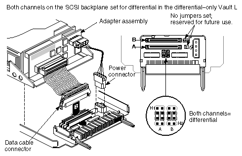
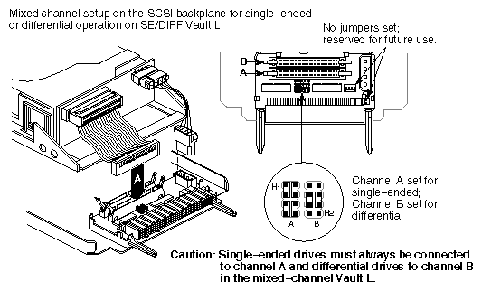
Determine which channel (A or B) you want the drive to occupy, then plug the SCSI cable from the drive into the proper channel connector. See Figure 2-1 and Figure 2-2.

Caution: Channel A on the mixed-channel Vault A is reserved for single-ended SCSI drives only. The drive sled board jumpers should be set for either differential or single-ended operation as shown in
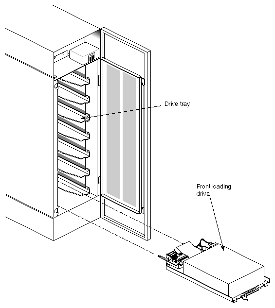
Figure 2-1 and Figure 2-2.To install a drive, orient the front-loading drive relative to the Vault L so that the drive is facing up. See Figure 2-3.

Caution: Always install drives beginning from the bottom to prevent the Vault L storage box from tipping over.
Carefully insert the device into the drive bay until it seats firmly into the lever catch and move the locking lever all the way to the right.
After you have installed all of the drives, you can power on the drive box and rack. See Figure 1-2 in Chapter 1, “Touring the Chassis,” earlier in this guide for the location of the power switch.
| Caution: Recheck the SCSI ID of the drives to make sure you do not duplicate numbers. |
Full-height drives require two half-height drive slots. To install a full-height drive, you must first remove a drive shelf from the Vault L using these instructions:
Open the front door of the Vault L.
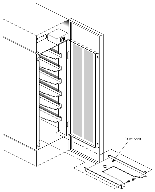
Select a drive shelf for removal, then remove the two screws that secure the drive shelf to the sides of the Vault L chassis (see Figure 2-4).
Pull the drive shelf out of the chassis and store it for later possible use.
Follow the instructions in the previous section, “Installing a Drive,” to insert a full-height drive in the Vault L.
Push the drive lever to the left to disengage the drive assembly from the shelf.
Carefully slide the drive and sled assembly out of the slot.
To notify the operating system of the new drives, run the MAKEDEV command, which creates the required device files for the software. If you do not know how to run MAKEDEV, refer to your system administrator's documents.
| Caution: Only a qualified system administrator or someone familiar with IRIX™ commands should execute MAKEDEV. |
The power switch for the Vault L storage box is located in the front, as shown in Figure 1-2 in Chapter 1, “Touring the Chassis,” earlier in this guide. It is recommended that you always power up the Vault L first before powering up the host system. If you need to bring down the entire system, turn off the Vault L first before shutting down the host system.
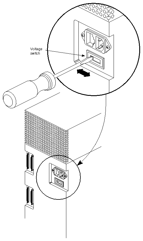
| Caution: The Vault L has a switchable 115/230 power supply. See Figure 2-5. To prevent damage to the Vault L storage box, always ensure that the voltage setting matches the power source voltage. |
