This chapter discusses the product configurations, and the controls and connectors visible from the front and rear of the Vault L storage box.
The Vault L is available in two configurations:
differential (which supports differential SCSI drives)
mixed-channel (which supports both single-ended and differential SCSI drives)
| Note: The “Rear View Components” section tells you how to distinguish between a differential and mixed-channel Vault L storage box. |
The Vault L operates with 8- and 16-bit differential drives and also 8-bit single-ended drives on the mixed-channel version. However, the Vault L does not support RAID (random array of inexpensive drive) devices and also does not currently support 16-bit, single-ended drives.
| Warning: This equipment is extremely sensitive and is susceptible to damage caused by electrostatic discharge (ESD). ESD is an electrical discharge (spark) caused by the buildup of electrostatic potential on clothing and other materials. |
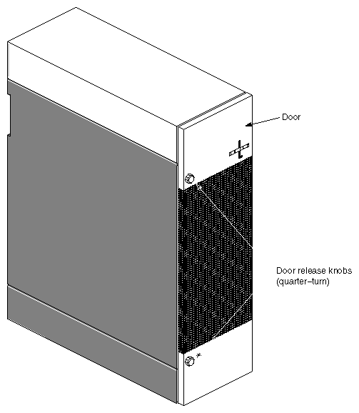
Figure 1-1 shows major components visible at the front of the Vault L storage box.
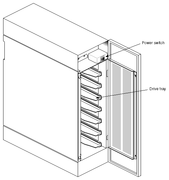
To open the door, push the knob in and turn it counter-clockwise. To close the door, push the knob in and turn it clockwise. Figure 1-2 shows the Vault L storage box with the drive door open.
The following components are located on the front of the Vault L storage box:
| Drive door | opens and closes using two quarter turns. Open the drive door by pushing the knob in and turning it counter-clockwise to open. Close the door by pushing the knob in and turning it clockwise. |
| Caution: The door must be in place during operation to comply with FCC regulations and for proper air flow. |
| On/Off switch | controls power to all the drives (see Figure 1-2). | |
| Drive shelves | house the SCSI drives and drive sleds. The shelves are removable to accommodate full-height drives. |
| Note: Each full-height drive occupies two half-height slots. |
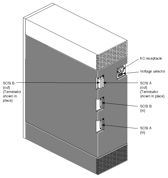
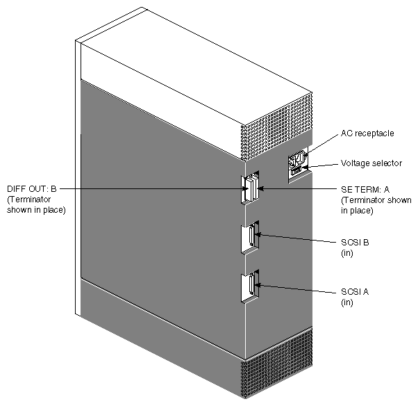
Figure 1-3 shows major components visible at the back of the Vault L differential storage box and Figure 1-4 shows the rear view of the mixed-channel configuration.
| Note: The mixed-channel version has a connector called SE TERM: A. This connector is not present on the differential Vault L storage box. |
| Note: This version supports both single-ended and differential drives. The mixed-channel Vault L also has a connector called SE TERM A. This connector is not pressent on the differential Vault L. |
The following major components are located on the back of the Vault L storage box:
SCSI In (A/B) provides a 68-pin SCSI-2 differential connector.
| Note: Each SCSI box provides two SCSI In connectors for disk striping and increased I/O throughput. |
| SCSI Out (A/B) | provides connection for SCSI termination or a daisy-chain connection to a second Vault L or another SCSI device. |
| Note: You must install a SCSI terminator as shown in Figure 1-3 and Figure 1-4 to properly terminate the SCSI bus line. If you are daisy-chaining to a second Vault L or another SCSI device, install the terminator on the SCSI Out connector of the second Vault L or the last SCSI device in the chain, as applicable. |
| Voltage Selector Switch |
|
| Caution: To prevent possible damage to the Vault L, always ensure that the voltage selection matches the power source input. |
| Warning: Do not attempt to connect the Vault L to the host system. Installation should be performed only by Silicon Graphics-certified personnel. Installation of these upgrades requires specific training and technical knowledge. This equipment utilizes electrical power internally that is hazardous if the equipment is improperly disassembled. This equipment is also extremely sensitive and is susceptible to damage caused by electrostatic discharge (ESD). ESD is an electrical discharge (spark) caused by the buildup of electrostatic potential on clothing and other materials. |


