This appendix supplies information about the Onyx IO4 PROM (Programmable Read Only Memory) Command Monitor. This information is separated into sections describing the PROM graphical user interface (GUI), the hardware configuration commands, the environment variables, and known bugs. Basic mezzanine board configurations on the IO4 and troubleshooting tips are also covered.
The IO4 PROM presents the user with a graphical interface when the console environment variable is set to “g.” In all cases, the keyboard can be used instead of the mouse, and in most cases the keystrokes required to perform a particular task are identical to those in previous IRIX releases.
For example, the main five-item panel that is displayed when the system first starts up is identical to the five-item menu found on previous systems. To select an option from the panel, you may use the mouse to click one of the five buttons on the left side of the panel, or you can press the corresponding number key. The top item (“Start System”) is option number one, and the last item (“Enter Command Monitor”) is option number five.
The IO4 PROM allows you examine and modify the hardware configuration of your system using a variety of commands.
When the system first powers on, the IO4 PROM automatically examines all of the installed boards to determine if any of the components have failed. During this process, the IO4 PROM reads a copy of the system's hardware inventory from nonvolatile RAM and compares it to the system's current configuration. If there are differences between the current and stored hardware inventories, the IO4 PROM inventory checker will generate a warning message. When a difference is detected during this comparison of the hardware inventory, the PROM pauses to allow you to examine the error messages. In the following example, the PROM detected a missing processor on an IP19 board:
Checking inventory... *** Slice 1 on the IP19 in slot 2 isn't visible Press <ENTER> to continue |
If system uptime is critical (for example, if your system is the central server) and operators are not available around the clock, you may not want the PROM to wait for operator intervention when the inventory checker notices a problem. You can configure the system so that it continues to boot in spite of nonterminal failures by setting the nonstop environment variable (see the “Environment Variables” section that follows).
Because the PROM's hardware inventory checker is incapable of telling the difference between missing and broken hardware, you must explicitly update the system's hardware inventory whenever you change the system configuration. Update the hardware inventory as follows:
Enter the PROM Command Monitor by selecting the “Enter Command Monitor” option from the PROM menu.
When the Command Monitor prompt (>>) is displayed, type update and press <Enter>. This tells the PROM that the system's current hardware configuration is correct.
Type reset and press <Enter> to reset your machine.
If you see error messages when there have been no modifications to the system's hardware inventory, it may indicate a component failure. Call your service provider and do not update the hardware inventory until a field engineer has examined the system.
Display a list of the boards currently installed in your system by typing
hinv -b. The -b causes bus-specific information to be displayed. The -v (verbose) option, when used in conjunction with -b, causes more detailed information about the boards to be displayed. For example, typing
hinv -b -v <ENTER> |
displays the configuration of all of the processors, memory banks, and I/O adapters in the system.
In the unlikely event of an extreme hardware failure, the system may drop down into a low-level diagnostic environment known as the power-on diagnostics (POD) mode. This mode is used as an aid to system diagnosis and is not intended for use by customers. If your system enters POD mode, contact your service provider.
This section describes procedures that you can use to customize certain aspects of the PROM Command Monitor. Many aspects of the system startup process can be individually tailored by changing the PROM environment variables. These variables are changed using the setenv command while in the Command Monitor. Enter the PROM Command Monitor by first selecting the “Stop for System Maintenance” option during the system startup. When the System Maintenance menu is displayed, enter the PROM Command Monitor by typing 5.
Some common modifications are described in the following subsections. Additional information is provided in the prom(1M) reference page.
The system can be configured to use a terminal connected to serial port tty_1 as the console by setting the console variable to “d” as follows:
setenv console d |
To change the console back to the graphics screen, set the variable to “g”:
setenv console g |
After setting the console variable, type init then press <Enter> to reinitialize the system and cause it to switch to the selected console device.
There are three environment variables in the PROM that are used to specify which device to boot from: the “SystemPartition,” the “OSLoadPartition,” and the “root” variable.
The “SystemPartition” variable specifies the location of the device volume header. Its default value is “dksc (0,1,8),” which specifies SCSI controller 0, disk 1, and partition 8 (by convention, the volume header is always
partition 8).
The “OSLoadPartition” variable specifies the device from which the IRIX kernel should be loaded. Its default value is “dksc (0,1,0),” which tells the PROM to look for the kernel in partition 0 of disk 1, on SCSI controller 0 (by convention, the kernel location is always partition 0).
The root variable tells IRIX the name of the device that holds the root filesystem. Because this variable is used by IRIX, rather than the PROM, its format is different from the “SystemPartition” and “OSLoadPartition” variables. The default value for root is “dks0d1s0,” which specifies that the root filesystem is stored on partition 0 of disk 1, on SCSI controller 0.
The following three examples show you what the command line looks like when you change the boot device.
To boot off of disk number 2 on controller 0, enter the following:
setenv SystemPartition dksc (0,2,8)
setenv OSLoadPartition dksc (0,2,0)
setenv root dks0d2s0
To boot off of disk number 1 on controller 1, enter the following:
setenv SystemPartition dksc (1,1,8)
setenv OSLoadPartition dksc (1,1,0)
setenv root dks1d1s0
To boot off of disk number 3 on controller 2, enter the following:
setenv SystemPartition dksc (2,3,8)
setenv OSLoadPartition dksc (2,3,0)
setenv root dks2d3s0
Each time that the system is powered up, the PROM waits for a brief period of time before starting the operating system. If the “Stop for System Maintenance” option is not selected, or if the <Esc> key is not pressed, the system loads the operating system from memory and begins to execute it. Setting the environment variable autoload to “yes” enables this feature. Setting autoload to “no” inhibits the automatic startup and causes the PROM to display the System Maintenance menu after running the power-on diagnostics.
By default, the PROM will stop and generate a warning message if it finds that a component has failed. However, the failure of a single processor or bank of memory may not be serious enough to prevent the system from coming up. To prevent a nonfatal hardware problem from stopping the system, set the nonstop variable to 1:
setenv nonstop 1
To ensure that the system displays a notification message in the event of any hardware failure, set the nonstop variable to 0:
setenv nonstop 0
The following subsections describe all of the known IO4 PROM bugs. Since the IO4 PROM is software-writable, these bugs will be fixed by PROM updates in future releases of the operating system.
A bug in the CD-ROM volume size code causes the SCSI driver to display an erroneous “No Medium Found” message if the CD-ROM drawer (caddy) is empty when the system is booted. This message can be ignored.
If an unexpected status or warning message is printed, the graphical user interface (GUI) will switch over to a text port to display the message. The PROM will continue to execute, but additional information will be displayed textually instead of graphically. This bug is usually seen if an informational message is displayed while the miniroot is loading during the install process.
Each Onyx system comes with one standard IO4 interface board. See Chapter 1 for a technical overview of the IO4. The primary IO4 in the system always supports the VME Channel Adapter Module (VCAM) board.
If you are unsure of the system's hardware configuration, enter the hinv command at the console, and you should see something similar to the following:
% hinv <Enter> |
4 250 MHZ IP19 Processors CPU: MIPS R4400 Processor Chip Revision: 3.0 FPU: MIPS R4010 Floating Point Chip Revision: 0.0 Data cache size: 16 Kbytes Instruction cache size: 16 Kbytes Secondary unified instruction/data cache size: 1 Mbyte Main memory size: 64 Mbytes, 1-way interleaved I/O board, Ebus slot 11: IO4 revision 1 Integral IO4 serial ports: 4 Integral Ethernet controller: et0, Ebus slot 3 Integral SCSI controller 1: Version WD33C95A Integral SCSI controller 0: Version WD33C95A Disk drive: unit 1 on SCSI controller 0 Graphics board GU1-InfiniteReality VME bus: adapter 0 mapped to adapter 45 VME bus: adapter 45 Integral IO4 parallel port: Ebus slot 11 |
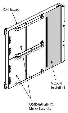
Each Onyx system is slightly different, but each has at least one IO4 installed. This determines the number of HIO mezzanine option boards it can support. It also determines the type of mezzanine options you can order. The VCAM on the IO4 precludes you from using “long” mezzanine boards. Long mezzanine boards stretch nearly to the backplane and do not fit on the IO4 when a VCAM is installed. Table D-1 describes some of the HIO mezzanine option boards and their lengths.
Table D-1. Optional Mezzanine Board Descriptions
Board Name | Size | Number of Connectors |
|---|---|---|
Flat Cable Interface | Long | 2 |
Flat Cable Interface | Short | 1 |
Three-Channel SCSI | Short | 3 |
Figure D-1 shows the configuration of the Onyx rackmount IO4. The IO4 uses a VCAM, and the IO4 may use up to two optional short mezzanine boards.
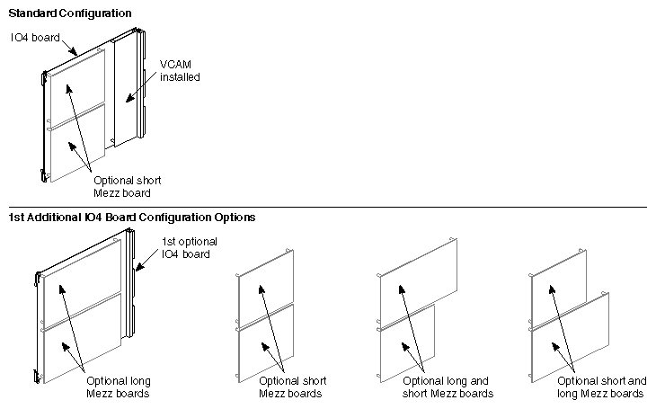
You can always have one or two short optional mezzanine boards installed on the primary IO4. This is determined by whether you have the visualization console option installed in your system. When you order a second optional IO4, you can have one of the following mezzanine configurations installed:
one or two long mezzanine option boards
up to two short mezzanine option boards
one long and one short mezzanine option board
Figure D-2 shows the optional second IO4 and the potential configurations for additional optional mezzanine boards that might be installed.
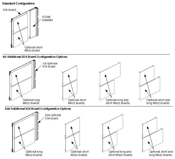
You can have one or two short optional mezzanine boards installed on the primary IO4. When you order a third optional IO4, you can choose the option of having one of the following mezzanine configurations installed:
Up to two long mezzanine option boards
Up to two short mezzanine option boards
One long and one short mezzanine option board
Figure D-3 shows both optional IO4s and the potential configurations for additional optional mezzanine boards that might be installed.
There are a number of troubleshooting steps you can use to determine if the IO4 is the cause of system-level faults.
Never plug the Ethernet connector in while the system is powered on. This action may result in a current surge that blows the filter on the I/O adapter or IO4. Symptoms resulting from this problem include
Ethernet not working
keyboard and mouse not working
powered peripheral ports not working
This problem requires a visit from a trained field service engineer.


