This chapter explains
For the procedures in this chapter, you need
the grounding wrist strap supplied with your Origin Vault option
a #2 Phillips screwdriver
Follow the steps in this section to prepare the Origin Vault rackmounted enclosure or standalone tower for component replacement.
| Warning: Removing the rackmountable Origin Vault enclosure from a rack or lifting the Origin Vault standalone tower requires two people. |
Have ready a clear work surface big enough to accommodate the option.
Have ready the replacement component and the grounding strap. If you are replacing anything besides the SCSI backplane, or if you have a standalone tower, have ready a #2 Phillips screwdriver.
Make sure no users are using the data stored in the expansion option. Check the status LEDs for each drive to make sure they are not active. If appropriate, follow proper shutdown procedures for the host to which the Origin Vault is cabled.
Turn off the power button at the front; the LED goes dark.
Turn off the master power switch at the rear of the Origin Vault.
If desired, remove drives from the option so that it is lighter when you move it to the work surface. If you do so, attach labels to them identifying the slots from which they came.

Caution: Replacing drives in different slots from their original slots can cause loss of data. Detach the power cable and SCSI cable(s) from the Origin Vault.
If the Origin Vault is padlocked, unlock it; see “Locking the Origin Vault Expansion Option” in Chapter 3.
If your Origin Vault is rackmounted, slide the enclosure out of the front of the rack with the help of another person.
| Warning: Removing the rackmountable Origin Vault option from a rack requires two people. |
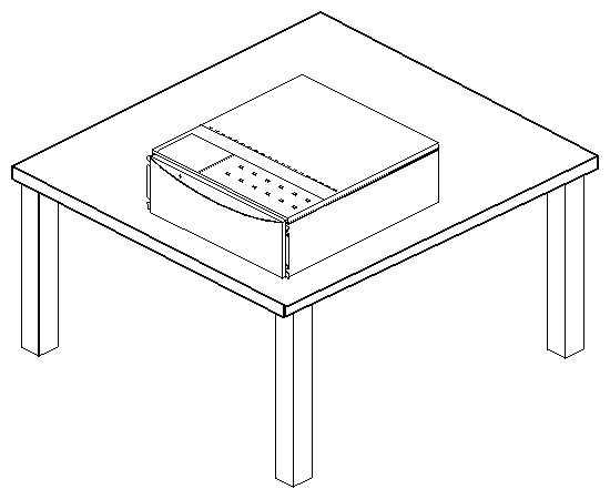
Place the rackmountable enclosure top-side up on the work surface, as shown in Figure 4-1. If the option is locked, unlock it; see “Locking the Origin Vault Expansion Option” in Chapter 3.
If your Origin Vault is a standalone tower, follow these steps:
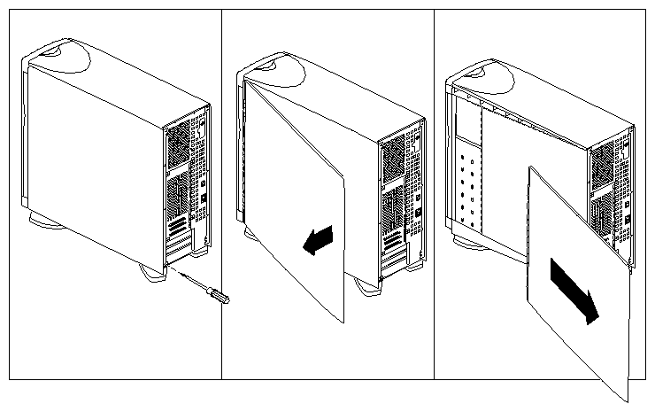
Remove the tower's side panels as shown in Figure 4-2.
Lay the tower on a work surface with the top cover facing up, as shown in Figure 4-1.

Warning: Lifting the Origin Vault standalone tower requires two people. You may wish to place a thin, soft pad (such as a cloth or piece of cardboard) under the top edge of the system to keep the top cap from becoming marred or scratched.
If the tower is locked, unlock it.
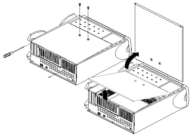
Remove the two screws at the rear of the chassis that secure the top cover and remove the top cover. See Figure 4-3.
Be careful not to touch components within the chassis.

Warning: Do not attempt to open the power supply at any time.
If you have a replacement backplane for the 3.5-inch drives, remove the old one and install the new one following these steps:
Prepare the Origin Vault for component replacement following procedures in “Preparing the Option for Component Replacement,” earlier in this chapter.
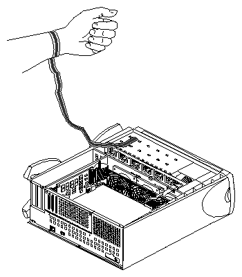
Ground yourself with a wrist strap, as shown in Figure 4-4.
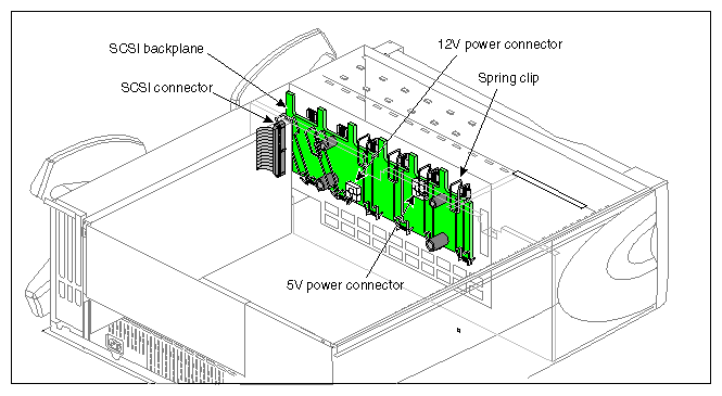
Detach the power cables from the SCSI backplane.
Note that the power cable plugs differ from each other. Figure 4-5 shows their location.
If you are able, detach the SCSI cable from its connector; otherwise, wait until the backplane is partway out of the chassis.
Snap down the six spring clips (see Figure 4-5) on the SCSI backplane.
Grasping the SCSI backplane by the edges, tilt it out. The backplane hangs on two pins; pull the backplane up off the pins.
With the board partway out of the chassis, unhook the SCSI cable at the left side of the SCSI backplane, if you have not already done so. Remove the backplane from the chassis and set it aside.
To insert the new SCSI backplane, hang it over the two pins and gently push it in at the bottom. Push the top of the board back as far as it will go.
Reattach the cables. Snap the six spring clips back up into place.
If you are finished replacing components, remove the wrist strap, replace the Origin Vault cover, and restore the Origin Vault to its working position.

Warning: Inserting the rackmountable Origin Vault option into a rack or lifting the Origin Vault standalone tower requires two people.
To replace a fan, follow these steps:
Prepare the Origin Vault for component replacement following procedures in “Preparing the Option for Component Replacement”.
Ground yourself with a wrist strap, as shown in Figure 4-4.
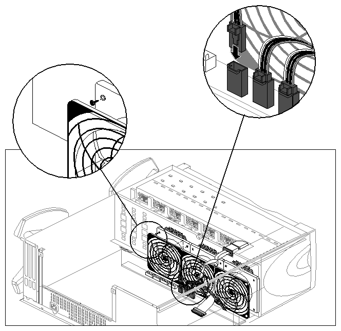
Unplug the power connector from the fan to the power supply, as shown in Figure 4-6.
Remove the two plastic rivets that hold the fan to the sheet metal, as shown in Figure 4-6. Push them out from behind the sheet metal with your fingertip.
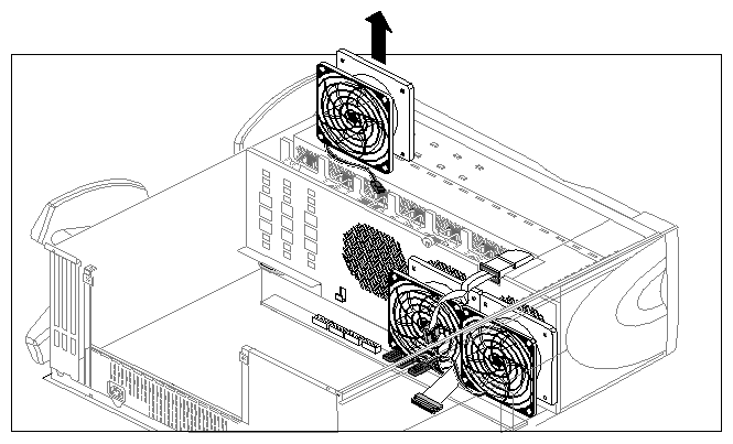
Lift the fan out of the system, as shown in Figure 4-7.
Follow these steps to install a fan:
If you have not already done so, prepare the Origin Vault for component replacement following procedures in “Preparing the Option for Component Replacement”.
If you have not already done so, ground yourself with a wrist strap, as shown in Figure 4-4.
Lower the new fan straight onto its connectors.
Snap a plastic rivet in the top corners of the fan to secure it to the sheet metal, as shown in Figure 4-6.
The rivet has two parts: a sleeve and a pin. Place the pin partway inside the sleeve, and then slide both through the hole in the fan.
Press the pin and sleeve together towards the sheet metal. The pin and sleeve slide into place with the ends of both protruding through the sheet metal.
Cable the fan, as shown in Figure 4-6.
If you are finished replacing components, remove the wrist strap, replace the Origin Vault cover, and restore the Origin Vault to its working position.

Warning: Inserting the rackmountable Origin Vault option into a rack or lifting the Origin Vault standalone tower requires two people.
To replace the board that converts the 3.5-inch drive controller from single-ended to differential, you remove the L-shaped converter board carrier (also known as the logic carrier—very different from the Origin200 server's logic carrier) from the chassis and remove the converter board from it. Follow these steps:
Prepare the Origin Vault for component replacement following procedures in “Preparing the Option for Component Replacement”.
Ground yourself with a wrist strap, as shown in Figure 4-4.
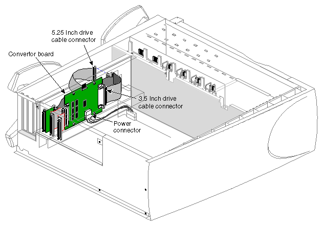
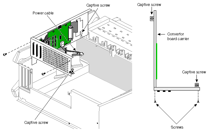
Detach the SCSI cable from the right end of the converter board and push the cable away from the board. See Figure 4-8.
Detach the cable to the 5.25-inch drive from the connector at the edge of the converter board carrier, as shown in Figure 4-8. Leave in place the 5.25-inch drive cable connecting the other side of this connector to the SCSI port on the converter board carrier.
With a #2 Phillips screwdriver, unscrew the four screws that secure the converter board carrier, as shown in Figure 4-9. The two screws toward the rear are retained in the carrier; reserve the other two screws.
Detach the converter board's power cable and place the converter board carrier on the work surface.
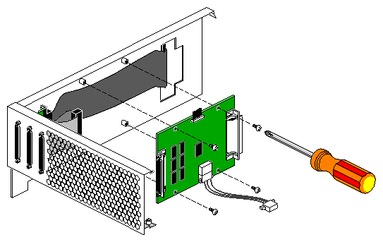
Unscrew the four screws that secure the converter board to the carrier, as shown in Figure 4-10. Reserve the two screws.

Caution: Take care not to damage the 5.25-inch drive cable behind the board. Detach the left-hand SCSI cable from the converter board.
Lift the old converter board away from the carrier.
Attach the left-hand SCSI cable to the new board's left-hand connector and insert the board; screw it in place, using the reserved screws.
Position the carrier so that you can reattach the converter board's power cable; plug it in.
Insert the carrier into the chassis; screw it in.
Reattach the cable to the 5.25-inch drive to the connector at the edge of the converter board carrier, as shown in Figure 4-8.
Reattach the SCSI cable to the right end of the converter board.
If you are finished replacing components, remove the wrist strap, replace the Origin Vault cover, and restore the Origin Vault to its working position.

Warning: Inserting the rackmountable Origin Vault option into a rack or lifting the Origin Vault standalone tower requires two people.
If the Origin Vault system controller board LED does not light up when the expansion option is powered on, you must replace it.
The system controller board is mounted on a carrier board. Inside the chassis, an edge connector on the system controller board is plugged into a connector on the backplane.
To remove the system controller board, follow these steps:
Make the system controller panel accessible by opening the door (standalone tower).
Ground yourself with a wrist strap, as shown in Figure 4-4.
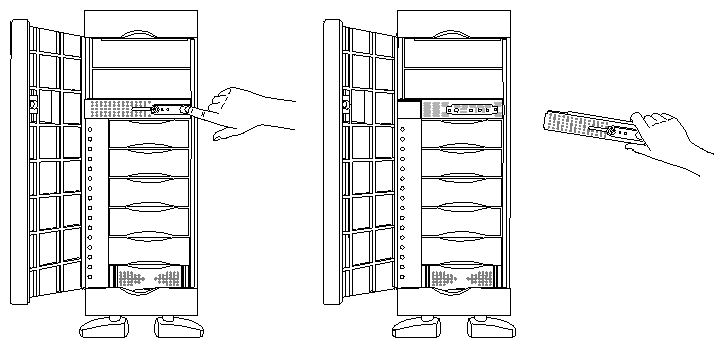
For the tower, or for a rackmounted Origin Vault option with the bottom-opening door, remove the crossbar, as shown in Figure 4-11, and set it aside.
For a rackmounted Origin Vault option with the side-opening door, snap the door and faceplate out of the brackets at the sides of the rack.
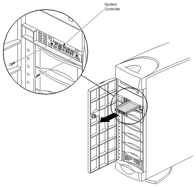
Unscrew the two screws that secure the system controller carrier to the front of the chassis, as shown in Figure 4-12.
Pull out the system controller assembly and lay it on a work surface.

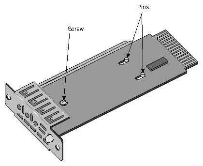
Caution: Be careful not to touch the board's edge connector (gold fingers). Remove the system controller board from its carrier; it is secured by a screw and two pins, as shown in Figure 4-13.
To install the replacement system controller board, follow these steps:
Position the replacement controller board over the pins; grasping the board by its sides, slide it so that the pins lock, making sure that the LED and button go through the proper holes. Screw in the reserved screw, as shown in Figure 4-13.
Remove disk modules 5 and 6 so that you can see the socket in the backplane into which the system controller's edge connector must go. If necessary, label the disks so that they are reinserted into the correct drive bays.
Insert the system controller assembly into its bay. If necessary, guide the board's edge connector into the socket.

Caution: Grasp the sides of the board only; do not touch the edge connector. When the edge connector is fully seated in the socket, the carrier should be flush with the front of the chassis.
Screw in the two screws that secure the system controller carrier to the front of the chassis, as shown in Figure 4-12.
Replace the crossbar and the faceplate with door.
To check whether the power supply is functional, follow these steps:
Prepare the Origin Vault for component replacement following procedures in “Preparing the Option for Component Replacement”.
Ground yourself with a wrist strap, as shown in Figure 4-4.
Connect the power cord to the Origin Vault.
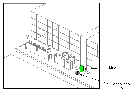
To check the health of the power supply, press the small button next to the power supply's LED, as shown in Figure 4-14.
If the LED fails to light, call your service provider to arrange for a replacement.
To replace the power supply, follow these steps:
Prepare the Origin Vault for component replacement following procedures in “Preparing the Option for Component Replacement,” earlier in this chapter. Make sure that the power cable is disconnected.
Ground yourself with a wrist strap, as shown in Figure 4-4.

Warning: Do not attempt to open the power supply at any time. Disconnect all internal cables from the power supply. If necessary, make a diagram for reference for when you reconnect the cables.
Remove the L-shaped converter board carrier (logic carrier) as explained in “Replacing the Differential/Single-Ended Converter Board” in this chapter.
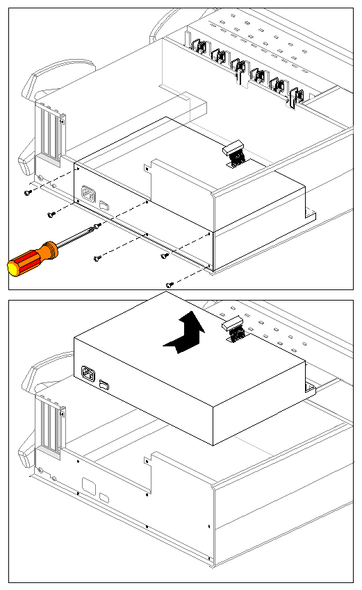
Disconnect the screws that secure the power supply to the chassis; see Figure 4-15.
Slide the power supply forward (towards the fans) until it unlatches from the chassis.
Lift the power supply out of the system. See Figure 4-15.
Follow these steps to replace the power supply:
If you have not already done so, ground yourself with a wrist strap, as shown in Figure 4-4.
Lower the power supply into the system and slide it back, away from the fans.
The latches on the bottom of the power supply and mating catches on the base of the chassis sheet metal should slide together.

Warning: Do not attempt to open the power supply at any time. Reconnect the power cord and test the new power supply as explained in “Checking the Power Supply”.
Replace the screws that secure the power supply to the chassis.
Replace the L-shaped converter board carrier (logic carrier) as explained in “Replacing the Differential/Single-Ended Converter Board”
Reconnect the internal cables.
If you are finished replacing components, remove the wrist strap, replace the Origin Vault cover, and restore the Origin Vault to its working position.

Warning: Inserting the rackmountable Origin Vault option into a rack or lifting the Origin Vault standalone tower requires two people.
