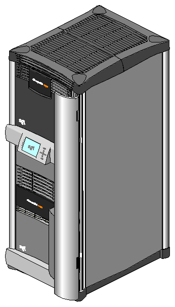
The Silicon Graphics Onyx2 rackmount system, model CMN A017, is a graphics supercomputer that is designed to meet the demanding requirements of visual simulation, post-production, multimedia, and distributed computing environments. The Onyx2 rack comes in a highly configurable and flexible system architecture that is available in a single rackmount or multirack system. The single rackmount system consists of two to eight 64-bit microprocessors, 128 MB to 4 GB of main memory, a wide variety of I/O interfaces, and one or two individual graphics workstation “pipes” (see Figure 1-1). The Onyx2 multirack configuration can use from 4 to 64 processors and support up to 16 individual graphics pipes. Note that special order systems with more than 64 processors are available; contact your SGI sales representative for more information.
This section lists the graphics, I/O, and supercomputing features of the Onyx2 rack system.
The rackmount Onyx2 provides features such as
one to sixteen graphics-pipe configurations
optional support of up to eight monitors on each pipe
an optional SuperWide (1920 x 1200) high-resolution monitor
MIDI baud rate and driver
beeping keyboard for support of “bell”
Other features of the Onyx2 rackmount system include
lower entry system cost than Onyx
scalable growth of memory and I/O bandwidth as well as processor compute power
support of a larger number of processors
high-availability within a single Onyx2 rack system
high bandwidth I/O connectivity
high total memory bandwidth
improved synchronization operations
large variety of peripheral connectivity options
This section provides an overview of the Onyx2 graphics rack system. The block diagrams used generally divide the system in two major functional parts, the I/O compute side and the graphics side.
The graphics hardware subsystem (also known as the graphics module) is generally contained in the top half of the Onyx2 rack. All direct graphics connections to monitors and other video devices are made at the back of the graphics module.
The processor computing subsystem is usually contained in the bottom half of the Onyx2 rack. This “compute” module supplies processing power, system I/O, keyboard/mouse, and analog and digital audio connections. Note that in multirack systems the compute and graphics modules may be mixed in different configurations than those shown in this section.
In an Onyx2 rack or multirack system each computing and graphics module has a dedicated module System Controller (MSC), which monitors module status. Each computing module can also have a separate set of hard disks, CPUs, I/O connections, and memory. Two or more computing modules can communicate using the high-speed (800 MBps) CrayLink Interconnect links. The CrayLink Interconnect (also known as the interconnection fabric) link consists of a set of high-speed routing switches and cabling that enables multiple connections to take place simultaneously. Using the CrayLink Interconnect, hardware resources (including main memory) can be shared and accessed by another compute module in multirack graphics system.
| Note: Not all multirack graphics systems have two computing modules; some may have only one. |
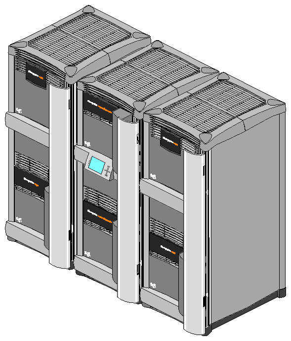
The single-rack Onyx2 is illustrated in Figure 1-1. The rack holds one graphics module and one processor compute module.
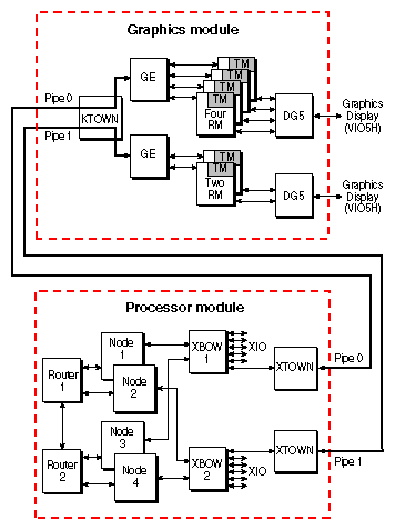
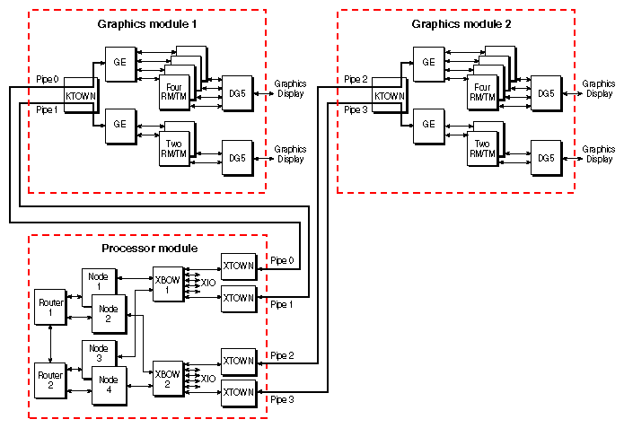
Figure 1-2 shows a block diagram example of the graphics rack's potential processor and graphics pipe configurations. The example shows a configuration with four Node boards and two fully loaded graphics pipes. Each system will vary based on the configuration ordered.
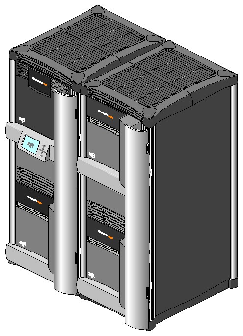
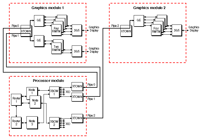
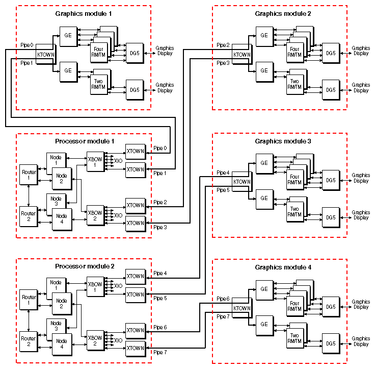
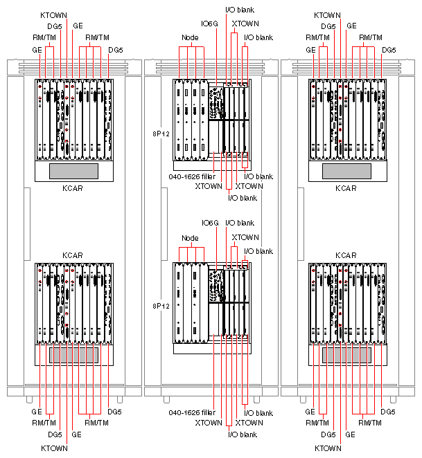
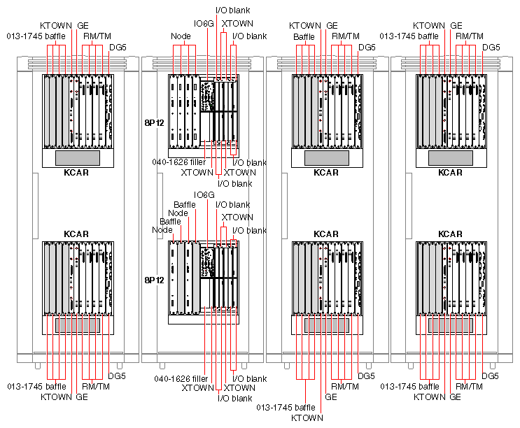
The multirack Onyx2 systems come in several configurations. The multirack Onyx2 system illustrated in Figure 1-3 is a dual rack system. This system can hold up to four modules. The example diagrams in Figure 1-4 and Figure 1-5 show a multirack system with a single compute module and three or four graphics pipes. The multirack Onyx2 system illustrated in Figure 1-6 is a triple rack system, also known as a RealityMonster system. From a software perspective, “monster mode” is used when more than one graphics pipe renders an image to a single video channel.
The configuration shown in Figure 1-6 can hold up to six modules (two compute modules and four graphics modules) and is available in different configurations. The example diagrams in Figure 1-7 and Figure 1-8 show a RealityMonster configuration of sixteen processors and eight graphics pipes. A RealityMonster configuration always requires an Ethernet hub to connect the multimodule System Controllers (MMSCs).
Figure 1-9 shows a four-rack configuration with six pipes and 12 processors. Each pipe uses four RM/TM assemblies.
The Onyx2 graphics subsystem contains one or two InfiniteReality2 board sets (pipes). One pipe holds one, two, or four RM/TM assemblies and the second uses one or two RM/TM assemblies. The major components of the graphics subsystem are
GE board
RM/TM assembly
DG5 board
VI05H (display daughterboard)
KTOWN interface (for connection to the compute module's XTOWN cable)
The major hardware components include the
64-bit microprocessor Node board(s)
System disk, MSC, and CD-ROM drive
Crossbow (XBOW) ASICs on the midplane
Router board(s)
BaseIO board (IO6G)
XIO slots
Each of these components are standard in the computing module.
The standard I/O subsystem consists of a BaseIO board assembly (also known as IO6G) that supports:
one 36-pin IEEE 1284-C compatible parallel port
four 9-pin serial ports (each port software selects for RS-232 or RS-422 operation)
one single-ended 68-pin Ultra SCSI and SCSI-2 compatible connector
two 6-pin mini DIN mouse connectors
two 6-pin mini DIN keyboard connectors
a 10/100-Mbps Ethernet connection (10Base-T or 100Base-T is automatically selected)
two analog stereo input 2.5 mm RCA-type jacks
two analog stereo output 2.5 mm RCA-type jacks
powered speaker 2.5 mm power jacks
stereo headphone or powered speaker output 3.5 mm stereo jacks
analog mono microphone input 3.5 mm jack
digital audio stereo input (AES-3id-1995) 75-ohm BNC jack
digital audio stereo output (AES-3id-1995) 75-ohm BNC jack
optical digital stereo input connector (8-channel ADAT)
optical digital stereo output connector (8-channel ADAT)
two loop-through video sync 75-ohm BNC inputs
Additional I/O connection capabilities are available with optional XIO boards.
The compute module in the Onyx2 graphics rack uses a new concept in symmetric multiprocessing systems that has a distributed shared-memory architecture called S2MP Architecture. This is a revolutionary (rather than evolutionary) technology step for SGI systems.
The Node boards within the Onyx2 compute module use links that differ from bus technology. While a bus is a resource that can be used by only one processor at a time, the communications “fabric” in the Onyx2 rack makes connections from processor to processor as they are needed. Each Node board contains either one or two processors, a portion of main memory, a directory to maintain cache coherence, and two interfaces:
The first interface connects to multiple I/O devices.
The second interface connects to the second Node board through the S2MP interconnect.
This web of connections differs from a bus in the same way that multiple dimensions differ from a single dimension. You could describe a bus as a one-dimensional line while the Onyx2 uses a multidimensional mesh.
The multiple data paths used are constructed as they are needed by router ASICs, which act as switches. When you add a Node board, you add to and scale the system bandwidth.
In the case of a multirack graphics system with more than one compute module, the CrayLink Interconnect links modules to one another. The CrayLink Interconnect may appear to be a type of super data bus, but it differs from a bus in several important ways. Basically, a bus is a resource that can be used only by one processor at a time. The Craylink Interconnect is a mesh of multiple, simultaneous, dynamically allocable connections that are made from processor to processor in the connected compute modules.
This makes the Onyx2 multirack system very scalable because it can range in size from 4 to 64 processors. As you add Node boards or compute modules, you add to and scale the system bandwidth.
The CrayLink Interconnect uses a set of switches, called routers, that are linked by cables in various configurations, or topologies. Here are some key features:
The CrayLink Interconnect is a mesh of multiple point-to-point links connected by the routing switches. These links and switches allow multiple transactions to occur simultaneously.
The links permit extremely fast switching (a peak rate of 1600 MBps bidirectionally, 800 MBps in each direction).
The CrayLink Interconnect does not require arbitration, nor is it limited by contention.
More routers and links are added as nodes are added, increasing the CrayLink Interconnect's bandwidth.
The CrayLink Interconnect provides a minimum of two separate paths to any pair of compute modules. This redundancy allows the system to bypass failing routers or broken fabric links. Each fabric link is additionally protected by a CRC code and a link-level protocol, which retry any corrupted transmissions and provide fault tolerance for transient errors.
Main memory on each Node board in the system can be distributed and shared among the system microprocessors. This shared memory is accessible to all processors in a compute module through the S2MP architecture. The CrayLink interconnection fabric provides inter-module accesses with low latency.
Each Node board in the graphics rack system is an independent memory source, and each Node board is capable of optionally supporting up to 4 GB of memory. A directory memory keeps track of information necessary for hardware coherency and protection.
Each Node board uses a HUB ASIC that is the distributed shared-memory controller. This ASIC is responsible for providing all of the processors and I/O devices with transparent access to all of distributed memory in a cache-coherent manner. Cache coherence is the ability to keep data consistent throughout a system. In the Onyx2 system, data can be copied and shared amongst all the processors and their caches. Moving data into a cache may cause the cached copy to become inconsistent with the same data stored elsewhere. The cache coherence protocol is designed to keep data consistent and to disperse the most-recent version of data to wherever it is being used.
Although memory is physically dispersed across the system Node boards, special page migration hardware moves data into memory closer to a processor that frequently uses it. This page migration scheme reduces memory latency—the time it takes to retrieve data from memory. Although main memory is distributed, it is universally accessible and shared between all the processors in the system. Similarly, I/O devices are distributed among the Nodes, and each device is accessible to every processor in the system.
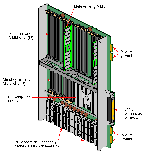
The Onyx2 graphics rack's microprocessor “brains” and primary memory are located on a processor board called a Node board. Each Node board in the Onyx2 graphics rack can house one or two 64-bit microprocessors. Each microprocessor uses a customized two-way interleaved data cache, and has dedicated second-level cache support. A high-performance bus interface links the CPU directly with supporting SRAM.
The Node board's main memory slots can be populated with 32 MB or 64 MB memory modules. See Figure 1-10 for an example Node board illustration.
Note that directory memory is used only in large scale multirack systems; there is no reason to use directory memory in a single-rack system.
XIO boards give the graphics rack system a wide range of optional interfaces in a manner similar to VME interfaces. Optional XIO boards can support communication interfaces such as
FDDI
Fibre Channel
HIPPI
Multiport Ultra (Fast-20) SCSI and SCSI-2
ATM
Multiport Ethernet
Check with your SGI sales or support representative for information on these or other optional interfaces available on XIO boards.
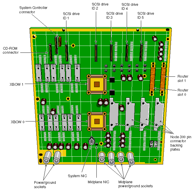
Each processor compute module in an Onyx2 graphics rack system uses a midplane. This means that boards, disk drives, and other devices can plug into both sides of the system. This allows for maximum functionality and expansion.
Single-ended Ultra SCSI and SCSI-2 disk, CD-ROM, and tape drives are the only devices internally supported by the Onyx2 graphics rack systems.
Figure 1-11 shows the front of the processor compute module's midplane.
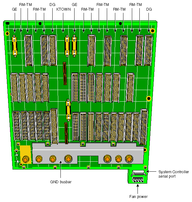
The rack system's graphics module uses a midplane in a similar way to the processor compute module. However, it does not have any disks or CD-ROM connections on the front. Only the MSC and power supply connections are made in the front. All graphics and interface boards go in the rear of the module and connect to the back of the midplane.
Figure 1-12 shows a view of the graphics module midplane.
This section covers the basic requirements for physical location of the rack to ensure proper chassis operation.
As a general rule, the rack system is intended for a lab or “machine room” environment.
The rack(s) should be protected from harsh environments that produce excessive vibration, heat, and similar conditions.
The rack system should be kept in a clean, dust-free location to reduce maintenance problems.
For questions concerning physical location or site preparation, see the Site Preparation manual for your system. If you are unable to find the information you need, contact your SGI System Support Engineer (SSE) or other authorized support organization representative.
Table 1-1 provides the basic physical specifications for the Onyx2 rack system.
Table 1-1. Rack System Physical Specifications
Parameter |
| Specification |
|---|---|---|
|
|
|
Dimensions: |
|
|
Installed: | length | 39 in. (99 cm) |
Shipping: | length | 81 in. (206 cm) |
Weight: | minimum (empty rack) | 300 lbs (136 kg) |
Floor Loading: | minimum | 38 lb/ft2 (185 kg/m2) |
Air Temperature: | operating (< 5000 ft) | 41 to 95 °F (5 to 35 °C) |
Thermal Gradient: | maximum | 18 °F (10 °C) per hour |
Altitude: | operating | 10,000 ft (3,048 m) MSL, maximum |
Humidity: | operating | 10-90% (non-condensing) |
Humidity Gradient: | maximum | 10% relative humidity per hour |
Acoustics: | typical | 55 dBa |
Vibration: | max. sustained, oper. | 5-10 Hz @ .01” total excursion, 10-500 Hz @
0.1g |
