Sirius Video blending can implement the full compositing algebra, computing an output value for three input sources, as well as input from the chroma key generator. On each input, a normalization control can scale the input RGB or YUV values by the selected alpha before blending.
 | Note: See Chapter 15, "VL Blending," of the Digital Media Programming Guide for background information on blending and keying. |
This chapter explains
using vcp to set chroma key generator values
using vcp to set blend function values
using VL chroma key generator node controls
using VL blend node controls
This chapter concludes with an example fragment.
 | Note: The gfxvidkeytovid program for the chroma key generator blends live video and graphics: it sets input, video output, and grab area, sets blender functions, sets values, ranges, and softness parameters for each component (A, B, and C), and creates special keys in a proprietary color space. This program is described in Appendix E, "Example Programs," later in this guide. If Sirius Video and Multi-Channel Option are installed on the same VME section of your system, Sirius Video is unable to use this program. |
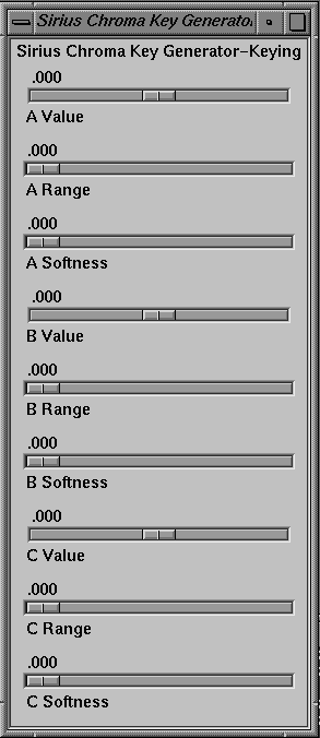
Use the "Sirius Chroma Key Generator" menu item in the vcp Pro menu to set levels—value, range, and softness (transition)—for the three input color components A, B, and C. By default, the color components A, B, and C correspond to V, Y, and U, respectively, but they can be set to RGB or any other color space with application software.
In the Pro menu, select "Chroma Key Generator Controls", and then select "Keying Controls". The Sirius Chroma Key Generator-Keying window appears, as shown in Figure 3-1.
In this window:
Value is
for the B (Y) channel: brightness
for the A (V) and C (U) channels: hue and saturation
all three
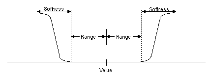
Range extends from each side of the value to the beginning of the transition.
If the input signal varies smoothly in color, the optional softness value, or transition, allows you to control the range of input colors, which translate to a partially opaque key signal.
Figure 3-2 shows the relationships between value, range, and softness (transition) for a single channel (for example, A).
See "Using VL Chroma Key Generator Node Controls," later in this chapter, for more information on chroma key generation.
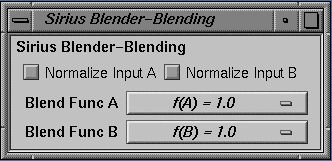
The blender has two inputs, path A and path B. Each has an associated alpha that is separately controllable. Sirius Video specific VL controls set these inputs; they are discussed in "Using VL Blend Node Controls," later in this chapter. Settings in the panel control blending of these paths.
To use the panel to set the blend functions that control mixing of frames from paths A and B, select "Blender Controls" in the Pro menu, and then select "Blending Controls". The Sirius Blender-Blending window appears, as shown in Figure 3-3.
Either source (Blend Function A or Blend Function B) can be background or foreground.
The choices for the two blend functions A and B correspond exactly, as shown in Table 3-1, although the order varies slightly.
Table 3-1. Choices for Blend Functions A and B
Blend Func A | Blend Func B |
|---|---|
f(A) = 0.0 | f(B) = 0.0 |
f(A) = 1.0 | f(B) = 1.0 |
f(A) | f(B) = f(A) |
f(A) = 1 - f(A) | f(B) = 1 - f(A) |
f(A) = f(B) | f(B) |
f(A) = 1 - f(B) | f(B) = 1 - f(B) |
The check boxes at the top of the Blender window set normalization on for each blending source. Normalized background pixels for a frame are premultiplied by their corresponding alphas before they are blended (Porter-Duff model).
Blending for Sirius Video can be based on the alpha value (opacity) that the chroma key generator determines for each pixel for one of the sources to be blended. Sirius Video generates this value by chroma extraction, luma extraction, or both.
The Sirius Video chroma key generation controls set parameters for three input color components, A, B, and C. By default, these components are V, Y, and U, respectively, but they can be changed by application software to R, G, and B, or any other color space via a Sirius Video control. The resulting alpha value can be used by the blender or passed on to the VME, video, or graphics outputs.
 | Note: Because keying parameters and some blending parameters are implemented as device-dependent VL controls, see Chapter 15, "VL Blending," of the Digital Media Programming Guide for background information on blending and keying. |
This section explains
the color key volume
color-space conversion
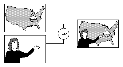
The chroma key generator creates a soft-edged rectangular color volume, considered to be transparent (its alpha is 0), which is the excluded region for keying. This region specifies both color and luminance; setting either the chroma or luminance range to 1 yields pure luma or pure chroma keying. The remainder of the YUV color space is considered opaque for keying. Luma keying is typically used to overlay a fixed image on video, such as the name and title of an individual being interviewed, a cable channel's logo, or a symbol that denotes an ongoing news story during a newscast. Chroma keying overlays one image on another based on the color value. Figure 3-4 diagrams a common chroma key application.
Each input color component (A, B, and C) has a value control, a range control and a softness control:
Value is:
for the B (Y) channel: brightness
for the A (V) and C (U) channels: hue and saturation
all three
Range extends from each side of the value to the beginning of the transition.
If the input signal varies smoothly in color, the optional softness value, or transition (computed with the formula 3x2 - 2x3), allows you to control the range of input colors, which translate to a partially opaque key signal.
 | Note: The gfxvidkeytovid example program, printed in Appendix C, enables the chroma key generator. |
Table 3-2 summarizes the controls for Sirius Video chroma key generation.
Table 3-2. Sirius Video Chroma Keying Controls
Control | Range | Sets... |
|---|---|---|
VL_SIR_KEYGEN_A_VALUE | -1..1 | Central value for channel A (default: V) |
VL_SIR_KEYGEN_A_RANGE | -1..1 | Range for channel A (default: V) |
VL_SIR_KEYGEN_A_SOFTNESS | -1..1 | Sharpness of transition for channel A (default: V) |
VL_SIR_KEYGEN_B_VALUE | -1..1 | Central value for channel B (default: Y) |
VL_SIR_KEYGEN_B_RANGE | -1..1 | Range for channel B (default: Y) |
VL_SIR_KEYGEN_B_SOFTNESS | -1..1 | Sharpness of transition for channel B (default: Y) |
VL_SIR_KEYGEN_C_VALUE | -1..1 | Central value for channel C (default: U) |
VL_SIR_KEYGEN_C_RANGE | -1..1 | Range for channel C (default: U) |
VL_SIR_KEYGEN_C_SOFTNESS | -1..1 | Sharpness of transition for channel C (default: U) |
VL_SIR_KEYGEN_MATRIX | Float matrix [3][3] | Key generator matrix, for example, changing from the default (YUV) to another color space, such as RGB |
The Sirius Video chroma key generator automatically converts from the input color space to YUV (CrYCb). For example, if the input is RGB, it converts using the CCIR values in Table 3-3.
Table 3-3. RGB to YUV Color-Space Conversion
| R | G | B |
|---|---|---|---|
Cr (V) | 0.50000 | -0.4900 | -0.08100 |
Y | 0.29900 | 0.58700 | 0.11400 |
Cb (U) | -0.16900 | -0.33100 | 0.50000 |
You can change the default YUV color space to RGB or another color space
with the matrix control VL_SIR_KEYGEN_MATRIX. The key generator matrix is concatenated to the precomputed matrix. For example, to perform key generation in RGB space, specify the values shown in Table 3-4.
Table 3-4. YUV to RGB Color-Space Conversion
| Cr | Y | Cb |
|---|---|---|---|
R | 1.401687 | 1.000000 | -0.000927 |
G | -0.714169 | 1.000000 | -0.343695 |
B | 0.000990 | 1.000000 | 1.772160 |
 | Note: For more information on color-space conversion, see Appendix D, "Sirius Video Color-Space Conversions," in this guide. |
The following example (a fragment from gfxvidkeytovid.c) illustrates setting the value of components:
/* Get denominator for the Key Generator fractions */
if (vlGetControl(svr, path, key, VL_SIR_KEYGEN_A_VALUE ,&val) < 0 ) {
     vlPerror("vlSetControl:KEYGEN:A_VALUE");
     exit(1);
}

/* Set A value */
val.fractVal.numerator = aval*val.fractVal.denominator;
if (vlSetControl(svr, path, key, VL_SIR_KEYGEN_A_VALUE ,&val) < 0 ) {
     vlPerror("vlSetControl:KEYGEN:A_VALUE");
     exit(1);
}
/* Set B value */
val.fractVal.numerator = bval*val.fractVal.denominator;
if (vlSetControl(svr, path, key, VL_SIR_KEYGEN_B_VALUE ,&val) < 0 ) {
     vlPerror("vlSetControl:KEYGEN:A_range");
     exit(1);
}
/* Set C Value */
val.fractVal.numerator = cval*val.fractVal.denominator;
if (vlSetControl(svr, path, key, VL_SIR_KEYGEN_C_VALUE ,&val) < 0 ) {
     vlPerror("vlSetControl:KEYGEN:A_softness");
     exit(1);
} |
The following example (a fragment from gfxvidkeytovid.c) illustrates the use of VL_SIR_KEYGEN_MATRIX.
/*
* The following is an example of using custom matrices to create
* special keys in a private color space.
*/

val.matrixVal[0][0] = 1.401687;
val.matrixVal[0][1] = 1.0;
val.matrix[Val0][2] = -0.000927;

val.matrixVal[1][0] = -0.71469;
val.matrixVal[1][1] = 1.0;
val.matrixVal[1][2] = -0.343695;

val.matrixVal[2][0] = 0.00099;
val.matrixVal[2][1] = 1.0;
val.matrixVal[2][2] = 1.772160;

if (vlSetControl(svr, path, key, VL_SIR_KEYGEN_MATRIX ,&val) < 0 ) {
     vlPerror("vlSetControl:KEYGEN");
     exit(1);
} |
The output of the Sirius Video chroma key generator can be passed to the blend node or any output node.
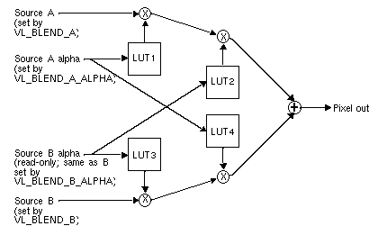
The Sirius Video blend node is supplied by up to four independent inputs:
Figure 3-5 diagrams the Sirius Video blend node.
The Sirius Video blend node has two multiplier stages, indicated by ⊗ in Figure 3-5, and one adder stage, indicated by ⊕. The values in the four lookup tables are based on the blending functions selected and on the input normalization controls. Table 3-5 gives some examples of compositing, assuming normalized inputs.
Table 3-5. Binary Compositing [a]
Operation | Diagram | f(A) = | f(B) = | |
|---|---|---|---|---|
Clear |
| 0 | 0 | |
A |
| 1 |
| |
B |
|
| 1 | |
A over B |
| 1 | 1-f(A) | |
B over A |
| 1-f(B) | 1 | |
A in B |
| f(B) |
| |
B in A |
|
| f(A) | |
A held out by B |
| 1-f(B) |
| |
B held out by A |
|
| 1-f(A) | |
A atop B |
| f(B) | 1-f(A) | |
B atop A |
| 1-f(B) | f(A) | |
A xor B (union of A out B and B out A) |
| 1-f(B) | 1-f(A) |
Normally, chroma is multiplied (scaled) by the selected alpha. For example, the value on source A can be multiplied by its own alpha value or that from source B. In a normal blend, f(A), the incoming alpha of source A is applied to the value for A. In the inverse of this blend, f(A)=1-f(A), the region that was considered opaque (turned off), that is, outside the volume defined for keying, is applied to source A.
In another way of blending, the alpha from source B can be applied to the component represented by source A. In the inverse of this blend, f(A)=1-f(B), the region that was turned off for source B is applied to source A.
The alpha for source B can be set to the chroma key generator; that is, values from the CKG are passed to the blend node as Bα. Thus Bα is either the alpha from source B or the value from the CKG. On the other hand, the values for source A and for source Aα can be specified independently of each other.
 | Note: The alpha for source B is read-only. |
Table 3-6 summarizes the VL controls that apply to the Sirius Video blend node.
Control | Values | Selects... |
|---|---|---|
VL_BLEND_A_FCN | VL_BLDFCN_ZERO VL_BLDFCN_ONE VL_BLDFCN_B_ALPHA (B source alpha)/255 VL_BLDFCN_MINUS_B_ALPHA: 1 ((B source alpha) / 255)
| Blend function that controls mixing of A source signals |
VL_BLEND_B_FCN | VL_BLDFCN_ZERO VL_BLDFCN_ONE VL_BLDFCN_A_ALPHA (A source alpha)/255 VL_BLDFCN_MINUS_A_ALPHA 1 - ((A source alpha) / 255)
| Blend function that controls mixing of B source signals |
VL_BLEND_A | VLNode type, derived from vlGetNode(); must be one of the two source nodes | A source image input |
VL_BLEND_B | VLNode type, derived from vlGetNode(); must be one of the two source nodes | B source image input |
VL_BLEND_A_ALPHA | VLNode type, derived from vlGetNode(); must be one of the two source nodes | A source alpha input |
VL_BLEND_B_ALPHA | VLNode type, derived from vlGetNode(); must be one of the two source nodes | B source alpha input |
VL_BLEND_A_NORMALIZE | (0,1) | Follows Porter-Duff model (B source pixels premultiplied by their corresponding alphas before blending) |
VL_BLEND_B_NORMALIZE | (0,1) | Follows Porter-Duff model |
VL_BLEND_OUT_NORMALIZE | Read-only; always on |
The following fragment (from gfxvidtovid.c) blends graphics input and video input.
/* Get the first Gfx input */
gfx_src = vlGetNode(svr, VL_SRC, VL_GFX, 0);
vid_src = vlGetNode(svr, VL_SRC, VL_VIDEO, 0);
/* Get the first Video output */
drn = vlGetNode(svr, VL_DRN, VL_VIDEO, 0);

blend = vlGetNode(svr, VL_INTERNAL, VL_BLENDER, VL_ANY);

/* Create paths */
path = vlCreatePath(svr, VL_ANY, gfx_src, drn);
if (path < 0)
{
     vlPerror("vlCreatePath");
     exit(1);
}

vlAddNode(svr, path, blnd);
vlAddNode(svr, path, vid_src);

/* setup path */
if (vlSetupPaths(svr, (VLPathList)&path,1, VL_SHARE, VL_SHARE) < 0)
{
     vlPerror("vlSetupPaths");
     exit(1);
}
/* gfx src controls */
origin.xyVal.x = xcoord;
origin.xyVal.y = ycoord;

size.xyVal.x = xsize;
size.xyVal.y = ysize;

if (vlSetControl(svr,path,gfx_src,VL_SIR_GFX_SIZE,&size) < 0 ) {
     vlPerror("vlSetControl:GFX SIZE");
     exit(1);
}

if (vlSetControl(svr,path,gfx_src,VL_ORIGIN,&origin) < 0 )
{
     vlPerror("vlSetControl:ORIGIN");
     exit(1);
}
/* Set the Blender A source to be the gfx source */
val.intVal = gfx_src;
vlSetControl(svr, path, blnd, VL_BLEND_A, &val);
/* Set the Blender A_ALPHA source to be the gfx source */
val.intVal = gfx_src;
vlSetControl(svr, path, blnd, VL_BLEND_A_ALPHA, &val);
/* Set the Blender B source to be the video source */
val.intVal = vid_src;
vlSetControl(svr, path, blnd, VL_BLEND_B, &val); |
