Active Surface Definition ( ASD) is a powerful real-time surface meshing and morphing library. It enables you to roam surfaces that are too large to hold in system memory very quickly. The surfaces, called meshes, are represented by triangles from more than one LODs.
ASD is a library that handles real-time surface meshing and morphing in a multiprocessing and multichannel environment. pfASD is an OpenGL Performer scene graph node that allows you to place ASD information in a scene graph.
This chapter describes how to create and use ASD.
In the past, OpenGL Performer applications have dealt with large surfaces in two ways:
Each of these approaches has its disadvantages:
When the entire surface is one LOD, with large surfaces, memory limitations often require such a high LOD that the resolution is poor.
Patches can only morph between adjacent LODs, which is insufficient in large surfaces. The result is visible borders between LODs.
Active Surface Definition (ASD) is designed to solve these problems. ASD is a powerful real-time surface meshing and morphing library characterized by the following features:
Transitions between different levels of detail ( LOD) appear smooth and void of spatial or temporal artifacts. Vertex position, normal, color, and texture coordinates can be morphed.
LODs can be generated using simple adaptations of well-known, non-uniform-tessellation surface subdivision algorithms.
ASD is real-time; in multiprocessor mode, it can sustain 60HZ operation while displaying complex surfaces.
Nearly-coplanar objects, such as road surfaces, are accurately represented in the non-uniform tessellation of each LOD using local textures.
Objects, such as buildings, may be modeled and rendered using alternate algorithms, yet remain attached to the surface.
Triangles substantially outside the viewing frustum are culled from rendering.
The evaluation function that specifies the morphing factor for each geometry is specified at run-time; this allows traversals to be optimized for different applications and data sets.
Huge surfaces, such as one-meter data of the entire United State, are supported using run-time paging from disk memory.
The pfASD approach uses a modeling surface that is a single, connected surface rather than a collection of patches.
An ASD surface contains several hierarchical level-of-detail (LOD) meshes, where one level encapsulates a coarser LOD than the next. When rendering an ASD surface, an evaluation function selects polygons from the appropriate LODs and constructs a valid meshing to best approximate the real surface on the screen.
Unlike existing LOD schemes, pfASD selects triangles from many different LODs and combines them into a final surface. This feature lets a fly-through over a surface use polygons from higher LODs for drawing nearby portions of the surface in combination with polygons from low LODs that represent distant portions of the surface.
To review an ASD application, see perf/test/simpleASD/simpleASD.C.
Modern computer graphics systems render objects represented by faceted surfaces comprised of triangles. While rendering performance is increasing steadily, it remains necessary to limit the number of triangles that are rendered if a real-time rendering rate of 60 frames per second or greater is to be maintained.
Triangles may be omitted with no loss of image quality if they represent objects that are not in the field of view (view frustum culling) or if they represent objects whose visibility is occluded by other, nearer objects.
The number of rendered triangles can also be dramatically reduced with little or no loss of image quality if multiple representations of each object are maintained, and the representation used has as little detail as is necessary for displaying a good-quality image. This technique and a body of others related to it are collectively referred to as level of detail (LOD) reduction, and the multiple-object representations are known as LODs.
LOD reduction is not a new idea, having been practiced in the field of real-time image generation for at least two decades. Early implementations eliminated the sudden, visible transition from one level of detail to another by alpha blending two models over a period of several frame times. More recently the fade transition has been replaced by a geometric morph solution, which eliminates the need to temporarily render additional triangles and interacts more nicely with depth buffer hidden surface elimination.
When the object being rendered is very large, there is no single level of detail that is optimal for the entire object. Instead, it is desirable to render the object with a smooth variation of level of detail; this allows nearer portions to be represented accurately, and farther portions to be represented efficiently.
The need for spatially varying level of detail is particularly acute when rendering terrain, which may range from several feet to hundreds of miles from the viewpoint. Early attempts to support multiple LOD terrain modeled the surface as separate tiles, each of which was rendered at a single level of detail. This approach results in physical discontinuities between neighboring tiles rendered with different levels of detail, which are visible as obvious ``walls.''
T riangulated irregular networks ( TINs) can approximate a surface with fewer polygons than other uniformly-grided representations. However, TIN models are hard to create dynamically at interactive rates. Regular data, on the other hand, allows easier construction of LODs at interactive rates. We propose a new terrain framework, Active Surface Definition (ASD), that combines the advantages of both regular and irregular networks. The terrain database is pre-computed and stored in a hierarchical structure of efficient, irregular triangulations. LOD reduction is performed on the data structure at real-time frame rates, varying levels of detail both spatially and temporally.
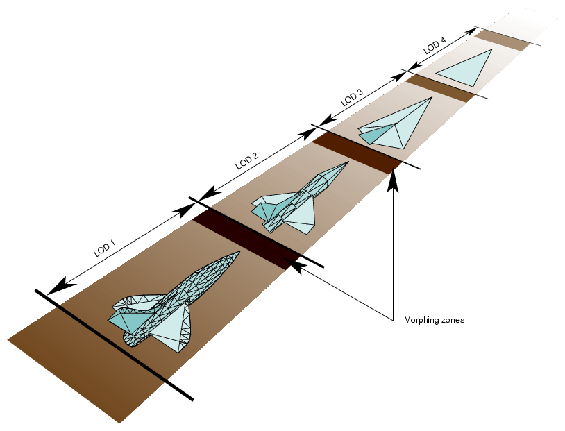
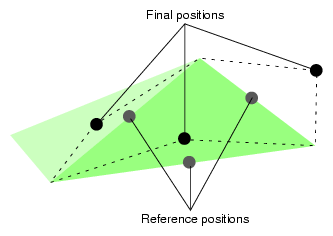
Active Surface Definition defines a hierarchical structure that organizes all the LODs of a terrain. At run-time ASD traverses the structure, selecting triangles from different LODs to render the portion of the terrain that is within the culling frustum. Triangles are rendered either at pre-stored locations when they are in a particular fully-morphed portion of a LOD range or at computed morphed locations when they are in the morphing transition portions of the LOD range, as shown in Figure 20-1.
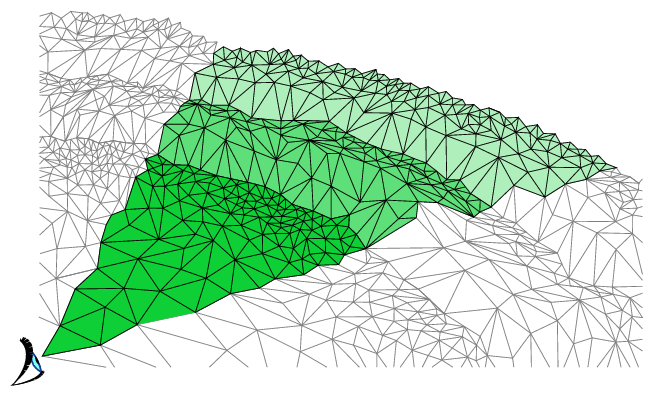
Figure 20-1 shows the complete object represented by an LOD. ASD is often used for very large terrains, like a map of the United States, where the entire terrain cannot fit into a single LOD range. In that case, parts of the large terrain would be represented by different LODs, as shown in Figure 20-2.
In Figure 20-2, different parts of the terrain are displayed at different levels of resolution.
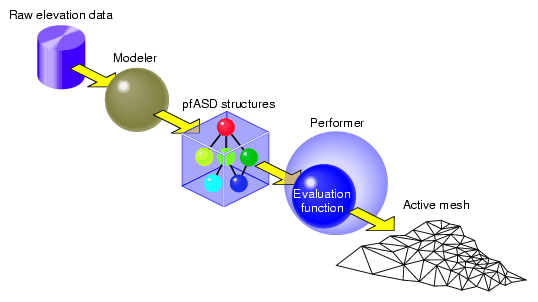
To visualize large terrains using ASD, you use the following steps, which are portrayed in Figure 20-3:
Collect raw, elevation data.
Use a modeler to create ASD structures from the raw elevation data. There are various triangle tessellation algorithms that can be used to model the terrain into TINs. Adaptive tessellation and accurate representation and minimum visual distraction between LODs are potentially all supported by pfASD structures.
Place the ASD structures into a scene graph by attaching them to pfASD nodes.
Design an evaluation function that shows when a particular triangle on a particular LOD level in ASD structure should be selected.
OpenGL Performer traverses and evaluates pfASD structures at run-time to create an active mesh that is used for rendering.
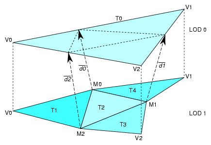
To demonstrate the ASD concept, we shall now build a very simple ASD surface. The surface has two representations, which corresponds to two levels of detail (LOD). The coarser level, LOD 0, has only a single triangle: T0. The finer level, LOD 1, has four triangles: T1, T2, T3, T4, as shown in Figure 20-4.
pfASD requires that we specify a morphing relationship for the vertices in the two levels of detail. This relationship guides ASD to choose triangles from the appropriate LODs and place vertices in the correct positions.
Each triangle in LOD 0 can have up to four replacement triangles in a higher LOD. pfASD imposes the limitation that the replacement of T0 must include the vertices V0, V1, V2, and may include three more vertices. In our case, the replacement of T0 includes the vertices V0, V1, V2, M0, M1, M2. We express the morph behavior between two levels by describing the morph behavior of the triangle vertices.
Since V0, V1, and V2 remain unchanged, we need only specify the morphing behavior, or the morphing vector, M0, M1, and M2. The morphing vector of a vertex is a vector connecting the vertex to an edge of the lower resolution triangle. We specify morphing vectors d0, d1, and d2 for the vertices M0, M1,and M2, respectively. The triangles in LOD1 can now morph smoothly by morphing the vertex M0, M1, and M2 along their morphing vectors d0, d1, and d2.
We call the edge position (M1+d1) unmorphed and, the M1 position fully morphed. The unmorphed position is the reference position of a vertex because it is a reference to show how a vertex should be coplanar with the triangle in the lower LOD when we replace the lower LOD triangle with a higher LOD triangles, while providing the least amount of visual distraction. The fully-morphed position is the final position of a vertex; that position should be chosen from the original raw data by various triangulation algorithms. It is recommended that the reference position be defined after the final position is chosen to most accurately design the adaptive tessellation of a terrain. pfASD handles the morphing of other attributes, such as normals, colors, and texture coordinates as well.
This completes the construction of a very simple pfASD. When flying over this model—for example, from V0 towards M1—pfASD shall morph M0 and M2 first and continue to morph M1 as we get closer to the edge [V1,V2]. In other words, pfASD will morph closer triangles into their higher LOD first.
pfASDs create active meshes to accurately and efficiently render terrains. A mesh is a surface tessellated into triangles, as shown in Figure 20-2. Each frame contains an active mesh. ASD reduces visual discontinuities between meshes by morphing geometry.
pfASD is defined by the following elements:
vertices
triangles
evaluation function
The triangles of all LODs share a single pool of vertices: those vertices that define the triangles of the highest LOD. A few vertices exist in all the LODs. These vertices define the triangles in LOD0 and are typically chosen as corners of the terrain or other significant features. Each of the remaining vertices exists in a contiguous set of LODs, including the highest LOD. In order to facilitate the gradual introduction of a vertex into the terrain, the actual position of each vertex is supplemented by a reference position. If i is the lowest LOD that includes a vertex, then that vertex is located at its actual position in LODs i through (n-1) and is morphed between its reference position and its actual position during the morphing zone of LODi, which is adjacent to LOD(i-1) range.
| Note: ASD could be extended to support multiple reference positions per vertex; this allows vertices to morph between multiple LODs. This extension may be supplied in the near future depending on demand. |
A vertex is represented by its final position (pfVec3) and a morphing vector (pfVec3), which represents the difference between the final position and the reference position. The current position of a vertex is computed in this manner:
Vvertex = V0 + mVd |
V0 is the final position of a vertex, m is the current morphing weight, and Vd is the morphing vector. Notice that the reference position of a vertex is always chosen to lie on an edge of a triangle from the lower LOD, though not necessarily at the centers of these edges. This is to ensure that the replacement of the lower LOD by the higher LOD happens when they are at coplanar positions; this eliminates sudden popping artifacts.
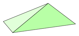
Attributes are represented by final position as well, as shown in Figure 20-5.
Normals, colors, and texture coordinates can all be linearly interpolated, as specified.
A vertex always morphs along the morphing vector, vd. When m = 1, the vertex is at a no-morph position, which means it most likely is not part of the active mesh, because it is on an edge of the parent triangle.
Triangles
A triangle exists in only one particular LOD. If the triangle is too coarse to accurately represent the current terrain, the triangle is removed from the active mesh. The position of a triangle is determined by the positions of its vertices, which may be morphed along the morphing vector.
In the pfASD structure, each triangle node, called an pfASDFace, can have up to four children. A sequence of frames may render the meshes shown in Figure 20-6.
As the distance between a vertex, P, and a viewer changes through the morphing range, the side of the triangle associated with P is replaced by two edges from the next LOD. Figure 20-7 shows how the next LOD triangles replace the current LOD triangles.
Figure 20-7 shows the shapes of the triangles in two adjacent LODs.
Notice that only one side of the triangle on the left is changed; in this case, the original triangle is now replaced by two triangles. The triangle that was on the right is now completely gone; in its place are four triangles, as labeled. One triangle can be replaced by up to four child triangles, depending on whether one, two, or three sides of the triangles are replaced by two lines.
Sides shared by two triangles are evaluated only once. Morphing the shared side of one triangle necessarily morphs it to the same position in the neighboring triangle.
The evaluation function determines the morph weight of every vertex. This function returns a floating point value between 0.0 and 1.0 where 1.0 means the vertex is not morphed and therefore not active. Since it is not active, it is not in the current mesh; its geometry is represented by coarser LOD triangles. 0.0 means that the triangle is completely morphed. In this case, the vertices are in their final positions in the active mesh. Any number between 0.0 and 1.0 signifies a morphed position. OpenGL Performer constructs a smooth mesh, based on the results from the evaluation function.
You can customize an evaluation function so that it applies to your application. For example, instead of distance, your evaluation function might be based on altitude.
For more information about the evaluation function, see “Default Evaluation Function”.
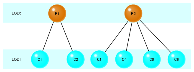
Raw geometry data is converted into a tree-like, hierarchical structure of data, as shown in Figure 20-8.
In Figure 20-8. each horizontal layer of triangles is equivalent to a single LOD mesh. The nodes in the tree structure represent triangles in LOD layers of the terrain. Each triangle contains three end vertices and up to three reference vertices. These vertices are indices into the vertex and attribute arrays.
A vertex may be shared by multiple triangles within a single LOD and by many more triangles throughout the data structure. A single position pair suffices for all the triangles that share a vertex, but each triangle may specify its own vertex attribute pairs. This is the reason that the vertex and attribute arrays are represented separately.
In Figure 20-8, the nodes in the top, root level represent the two LOD0 triangles shown in Figure 20-6. The six triangles from LOD1, labeled C1 through C6, correspond to nodes from the second level in the tree.
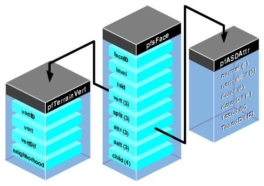
OpenGL Performer uses three data structures to encapsulate the triangle mesh information:
Triangle—Encapsulates information about the sides, vertices, attributes, reference points, parent, and children of a triangle.
Attributes—Encapsulates information about the attributes of each vertex, including the normal, color, and texture coordinates.
Vertex—Encapsulates information about a morphing vector and the coordinates of its final position.
Figure 20-9 shows the data structures, their fields, and their relationships.
The following sections describe these data structures in detail.
The triangle data structure in PFASD contains information about the triangles in the triangle mesh.
typedef struct pfASDFace { int level; int tsid; int vert[3]; int attr[3] int refvert[3]; int refattr[3]; int child[4]; int refvert[3]; ushort gstateid; ushort mask; } pfASDFace; |
Table 20-1 describes the fields in the triangle data structure.
Table 20-1. Fields in the Triangle Data Structure
Field | Definition |
|---|---|
level | Triangle's LOD level. |
tsid | Triangle strip ID. |
vert[3] | Coordinates of the triangle's three vertices. |
refvert[3] | Coordinates of the triangle's (up to) three reference points. |
attr[3] | Pointer to attribute values for each of the triangle's three vertices. |
refattr[3] | Pointer to attribute values for each of the triangle's (up to) three reference points. |
child[4] | Triangle IDs of the triangle's (up to) four child triangles. |
gstateid | GeoState ID. |
mask | Specifies whether or not to render the triangle. |
Each triangle in the database has an ID. Since one triangle can be replaced by as many as four triangles, child[4] is an array of child triangle IDs. The child IDs may be listed in any order in the array. Do not list the same child more than once in the child array.
If a triangle does not have four children, as is the case of the triangle on the left in Figure 20-7, enter the token PFASD_NIL_ID in the child[4] array where normally you would enter the IDs of the child triangles.
An ASD node may very likely have more than one texture in it; so, it contains more than one pfGeoState; one for each texture. gstateid specifies the pfGeoState object the triangle face uses.
There are times when you might like to have a triangle face specified in the structure but not draw it. For example, you need the triangles of the ground under an airport so that you can place the airport on it. However, since the triangles are covered by the airport, you do not want to render them. mask allows you to prevent the rendering of the triangle face specified in the structure.
As shown in Figure 20-8, each triangle is resident in a particular LOD level. level defines the LOD of the triangle. If the viewer is moving within one LOD, chances are they need to see other triangles at the same LOD level.
There are many cases in which you can have neighboring triangles with discontinuous LOD levels; for example, a high-resolution insert of a scene might be LOD level 5 and surrounded by triangles of LOD 1.
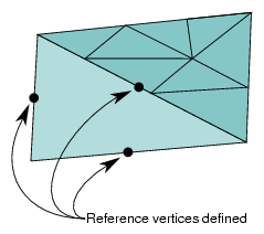
When neighboring triangles have discontinuous LOD levels, the lower-resolution triangles must have the following, as shown in Figure 20-10:
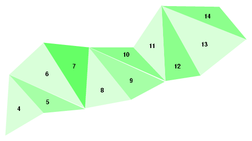
You can increase the rendering speed of your application by using triangle strips. Triangle strips are groups of contiguous triangles that together form a strip, as shown in Figure 20-11.
Triangle strips improve rendering performance because, after the first triangle in the strip, each additional triangle can be added by defining only one additional vertex.
The pfASD does not generate triangle strips dynamically. Triangle strips are pre-generated at modeling time and represented using tsid in the pfASDFace structure. Only triangles from the same ASD face tree level can be in the same triangle strip. The tsid numbers are sorted at run-time to connect as many triangles from the same triangle strips together as possible. Triangles with consecutive tsid values are placed in one triangle strip.
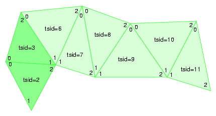
Figure 20-12 shows an example of a set of triangles with consecutive tsid values.
pfASD generates a triangle strip from the vertices marked 0, 1, and 2 in the triangle with tsid=2, followed by the vertex marked 2 in the triangle with tsid=3. The triangle with tsid=6 marks the beginning of the next triangle strip, vertices marked 0, 1, and 2 in triangle with tsid=6, followed by vertices marked 2 from triangles with tsid 7, 8, 9, 10, and 11. It is very important to start a triangle strip on an even triangle strip ID. For example, triangles in the first triangle strip can have IDs 0, 1, 2...; but they cannot have 1, 2, 3,... Vertices should be listed in pfASDFace in counter-clockwise order with the last vertex to be the vertex in the triangle strip.
At the termination of a triangle strip, there must be a non-consecutive tsid in the next triangle, as shown in Figure 20-12. Assigning the numbers 3 and 6 forces these triangles into separate triangle strips. Assigning all triangles to the same tsid would separate all of them into strips with only one triangle.
| Note: pfASD sorts all the visible triangles by tsid. tsid values, therefore, must not overlap in different areas of the surface. pfASD does not check that triangles with consecutive tsid values are indeed neighboring. |
The vertex and reference point arrays, vert[3] and refvert[3], each contain three pfASDVerts, which are the coordinates of the vertices and reference points. For more information on pfASDVert, see “Vertex Data Structure”.
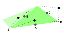
The order of the vertices and the reference points in the arrays must be counter-clockwise, as shown in Figure 20-13.
Any of the vertices can be the first in the array. The first reference point in the array, however, must be the one on the side between the first and second vertex points; for example, the reference point on the hypotenuse of the triangle in Figure 20-13 should not be entered as the first reference point in the refvert{3] array because the bottom leg of the triangle contains the first two vertex points entered into the vert[3] array.
If a triangle does not have three reference points, as is the case of the triangle on the left in Figure 20-5 (where only the hypotenuse has a reference point), enter the token PFASD_NIL_ID in the refvert{3] array where normally you would enter the indices of the reference points.
Each vertex can have its own set of attributes. The attribute format is described in “Attribute Data Array”. The arrays, attr[3] and refattr[3], point to three vertex attribute array entries and three reference point attribute array entries.
If a vertex or reference point is not assigned an attribute, enter the token PFASD_NIL_ID in the attr[3] or refattr[3] arrays where normally you would enter the pointer to the attribute array.
Each vertex and reference point can be assigned an attribute. An attribute is an interleaved list of floats that consists of normal, color, and texture definitions, as follows:
float normal[3]; float normalDif[3]; float Color[4]; float ColorDif[4]; float Tcood [2]; float TcoodDif [2] |
If any attribute is not defined, it should not be represented in the array, in which case the stride is shorter.
Each attribute has two listings: the values of the attributes at the final positions and how much they change during morphing. For example, the normal[3] array specifies the vector that is normal to the vertex at the final position while the normalDif[3] array specifies the difference between the normal and its final position and the normal at its reference point.
Color{4] and ColorDif[4] similarly specify the RGBA values at a vertex and the color morphing vector.
The texture coordinates, Tcood [2] and TcoodDif [2], specify the texture coordinates of vertices at their final position and the texture coordinates of the morphing vector.
The attribute array of floats can contain normal, color, and texture coordinate information, or it can contain any combination of attributes. You specify which of the attributes are in the attribute array of floats by setting the pfASDAttr() mask. To specify that you are including some or all of the attribute values in the attribute array, you use pfASDAttr() with one or more of the following tokens ORed together:
For example, to specify normal and color attributes only, use the following statement:
pfASDAttr(PFASD_NORMAL | PFASD_COLOR); |
If certain attributes are not specified in pfASDAttr, they should not be included in the attribute array. pfASD only takes one set of per-vertex-per-face attributes and one set of overall attributes.
If you want to use the same attribute value for all normals, colors, or texture coordinates, you can specify a global attribute value rather than making the same entry for each normal, color, or texture coordinate attribute. To specify a global attribute, use the following statement:
pfASDAttr(..., PFASD_OVERALL_ATTR, attr); |
attr, an array of floats, holds a set of attributes and their morphing vectors. You can mix a global attribute with a different attribute that is per vector.
The vertex data structure, defined as follows, holds the coordinate information of vertices and their vertex vectors.
typedef struct pfASDVert
{
    pfVec3 v0, vd;
    int neighborid[2];
    int vertid;
} pfASDVert;
|
Each vertex has an ID, vertid; a set of coordinates, vo; and a vertex vector, vd. The vertex vector is the vector stretching from the final vertex toward the reference point.
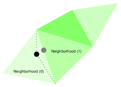
In a triangle strip, a line segment is commonly shared by two adjoining triangles, as shown in Figure 20-14.
The new vertex is shared by the adjoining triangles. Those triangles are referred to as the neighborhoods of the vertex. The neighborhood array contains the triangle IDs of the adjoining triangles in the previous LOD.
If a side is not shared by two triangles, then one of the neighborhood array values should be PFASD_NIL_ID.
The default evaluation function, which returns a value between 0.0 and 1.0, is based on the distance between the vertex and the eyepoint: the farther away a vertex is, the lower its resolution.
To use the default evaluation function, you must fill in the pfASDLODRange structure for each LOD.
typedef struct pfASDLODRange
{
    float switchin;
    float morph;
} pfASDLODRange;
|
LOD[i].switchin is the far edge of the LOD[i]. Take any vertex of a triangle in LOD[i] and compute the distance between the vertex and eyepoint. If this distance is more than LOD[i].switchin, the morphing weight of this vertex is 1.0 (NO_MORPH). If it is less, the morphing weight is calculated against the morphing zone.
LOD[i].morph is the length of the morphing zone from the LOD[i].switchin far edge. The morph weight is (1-(LOD[i].switchin-dist)/LOD[i].morph). If the distance is less than LOD[i].switchin - LOD[i].morph, the morph weight is 0.0 (COMPLETE_MORPH).
The evaluation function can be based on many things beside distance. For example, you might implement the evaluation function based on the following:
Line of sight—Geometries directly in front of the camera have the highest resolution while geometries more peripheral have a lower resolution.
Direction—High-resolution LODs appear only in one direction; for example, given the fuzzy nature of clouds, when a pilot looks straight ahead, the clouds do not need to be rendered with great detail. When the pilot looks down, however, you might like them to see the terrain in great detail.
True size of projected triangle—Triangles are replaced when they physically reach a specified size on the projector screen.
Event driven—An event triggers a change of LODs, for example, when a bomb explodes.
Shape—Specific shapes in the scene, perhaps a tank, could be rendered in higher resolution than the surrounding countryside.
None of these evaluation criteria can use the default evaluation function. Instead, you must write your own evaluation function and register it as a callback function with pfASD using the following method:
extern void pfASDEvalFunc(pfASD* _asd, pfASDEvalFuncType _eval); |
The evaluation function you provide, eval, must return a float between 0.0 and 1.0 and conform to a fixed format. pfASDEvalFuncType takes the argument vertid, which is the index of the vertex from the next LOD whose reference position is on this edge. Refer to asdfly/pfuEvalFunc.c for examples.
pfASD supplies a query mechanism for two kinds of objects:
vertices with a down vector
A vertex query answers the question: Where does the ray through the vertex in the given down direction hit the surface?
triangles with a projection vector and a down vector
A triangle query answers the question: given a triangle, how does it project onto the current morphing pfASD? Or, given a triangle, supply a list of triangles describing the projection of this triangle on the surface.
The pfASD has a mechanism for manipulating arrays of vertices and triangles and for reporting query results of surface geometries. Query results are kept in a pfFlux buffer. The application may read this buffer directly or connect it to a pfEngine for processing.
These query mechanisms must run in sync with the evaluation function. The query results must be used in the same frame that the morphing status of a pfASD becomes active. To synchronize the behavior of pfASD geometry and query points, you need to set the correct pfFlux flags, as described in “Aligning Light Points Above a pfASD Surface Example”.
Before describing the technical details of setting up a query array, the following section describes how to use these arrays.
In the visual simulation arena, you often place objects on surfaces. Since the pfASD surfaces morph, the objects on top must move to remain on the surface. Some objects require only position changes. Others require angle changes as well. A building on top of a mountain side, for example, requires only a position change to match the current altitude of the surface under it. A car standing on the same mountain side, however, requires changing both its position and its angle in order to remain aligned to the surface.
In the case of the building, it is enough to query the intersection between a query ray and the surface. In the case of the car, however, you must also calculate the surface normal at the intersection point.
We often wish to cast the shadow of objects on the surface underneath them. Since the pfASD surface is morphing, we must morph the shadows accordingly. Given a triangle and a projection direction, we want to project the triangle on the surface and tessellate its projection so that we get a 3D representation of the shadow. We can later use these shadow triangles as decals to paint the shadow on the surface.
Many times you wish to draw decals on a surface. In the context of surfaces, you may wish to add a road as a decal on the morphing surface. To make the road touch the surface, you must tessellate the polygons of the road so they conform to the shape of the surface. To tessellate the road, you project a triangle downwards and then tessellate the result.
To add an array to the pool of queries, you use the following:
Both methods require a pfFlux as input. After completing the evaluation of a pfASD frame, pfASD fills the specified pfFlux objects with query results for all the visible query arrays. The query results become relevant at the next pfFrame along with the newly evaluated pfASD geometry.
To make sure the query results are used only when their corresponding geometry is active, add the corresponding pfFlux and the pfASD node to the same sync group using pfASD:: setSyncGroup() and pfFlux::setSyncGroup().
A channel is a view of a scene. There are three approaches to linking multiple channels:
Each channel uses the same database, the same viewpoint, the same evaluation function, and the same LODs, but the viewing angle is different for each channel.
The effect is multiple channels that together create a continuous view like that of a horizon. The views of the scenes in each channel move together. For more information on this approach to multiple channels, see “Controlling Video Displays” in Chapter 17.
Each channel uses the same database, a different viewpoint, the same evaluation function, and potentially different LODs.
The effect is two or more views of the same scene; for example, one view might look along the terrain and another view might look down at the same terrain from above. This approach uses the pfASD API for creating multiple channels, as described in “Connecting Channels”.
Each channel uses the same database, a different viewpoint, different evaluation functions, and potentially different LODs.
The effect is two or more views of potentially unrelated parts of a scene; for example, if the database is the earth, one view might be of someone traveling around the north pole and another view might be of someone traveling around the south pole.
Because the only thing common to the two views is the database, you need to create two pfASD objects, one to handle each view.
The following section explains how to do the second approach to connecting channels.
When you have two channels that share the same database and evaluation function and differ only in that they have different viewing angles of the same part of a scene, you can save processing time and save memory by attaching the two channels using pfChanASDattach(); pfChanASDdetach() detaches two channels.
By making the two channels part of the same pfASD, processing time is improved because only one evaluation function is computed. Having one pfASD instead of two saves memory because two pfASDs requires maintaining two sets of the same scene.
A pfClipTexture is able to manage very large bodies of data, presenting only the part that is in view of the user. pf ASD modifies the pfClipTexture such that the different parts of the pfClipTexture are presented using the correct LOD level.
To use a pfClipTexture as part of a pfASD, use the following procedure:
Put the pfClipTexture into a pfGeoState.
Set the pfGeoState to a pfASD.
pfASD accepts a list of pfGeoStates.
Define the center of the pfClipTexture in one of two ways:
Attach a pfuClipCenterNode to a pfASD, as shown in the .im loader.
Use pfuTexGenClipCenterNode and convert the eyepoint through texgen into texture space as the clipcenter. This technique should be used when cliptexture is applied using texgen.
Set the proxy box equal to the rough boundary of the pfASD database. The boundary of the pfASD can be queried by calling pfGetASDBBox(asd, box).
Use a PRE callback function with pfASD to set the clip center yourself. To see an example, refer to terrain.c.
If the clip texture is virtual, pfASD automatically sorts geometry into concentric cliprings to support the appropriate cliptexture limit and offset. Set the environment variable, PFASD_CLIPRINGS to activate this feature. See libpfdem and libpfevt for examples.
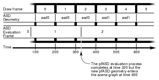
The pfASD evaluation function commonly runs as a separate, asynchronous process. This process does not necessarily finish its evaluation when the App-Cull-Draw frame finishes. The new pfASD geometry becomes active (visible) at the end of the pfFrame that follows the completion of the pfASD evaluation.
For example, if Draw frames 0, 1, 2, 3, 4... end at times 100, 200, 300, 400, 500... and the pfASD evaluation finishes at time 320, the new geometry is introduced into the scene graph at time 400, as shown in Figure 20-15.
In Figure 20-15, it is important to align objects to the old geometry in Draw frame 2 and to align to the new geometry in Draw frame 3.
The query results must affect the aligned geometry in the same frame that the pfASD geometry becomes active. To achieve this, you must connect both the pfASD node and Matrix-Flux to the same sync group. In this way, when pfASD changes the active surface geometry, it also activates the newly calculated query results.
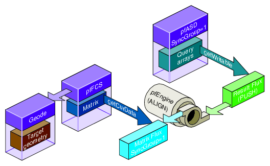
In general, you should move as much processing to the pfASD process as possible. In Figure 20-15, all the query/alignment operations take place in the pfASD process. Since the entire evaluation is triggered by the query array writing to Result Flux, the generation of the new pfFCS matrix in Matrix Flux also takes place in the pfASD process. The only change to the time critical APP-CULL-DRAW sequence is a single pfFlux::getCurData() to get the updated pfFCS matrix.
To align some geometry to a pfASD surface using query points, use the following procedure:
Pick an anchor point where you want the target geometry to go.
Generate a query array containing the anchor point and add it to pfASD.
Request pfASD to store the query results in the pfFlux marked Result Flux.
Generate an additional pfFlux and connect it to the pfFCS node matrix controlling the target geometry.
Figure 20-16 diagrams this procedure.
At run-time pfASD does the following:
pfASD starts its frame by evaluating the ASD surface and generating optimized geometry for it.
pfASD calculates the query array values.
pfASD writes the results into the pfFlux marked Result Flux.
The write operation triggers a calculation of the pfEngine because the Result Flux is a PUSH flux.
The pfEngine generates a transformation matrix and stores it in the pfFlux marked Matrix Flux.
The pfFCS node controlling the transformation of the target geometry has a fluxed matrix.
When the pfFCS node is traversed, it retrieves the newly generated matrix from Matrix Flux and uses it to align its child geometry.

Note: If you run the pfASD evaluation function in a separate process, the evaluation of the query arrays may happen asynchronously at some point during the OpenGL Performer frame.
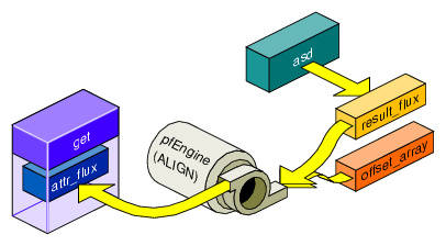
The following example, diagramed in Figure 20-17 demonstrate how to link pf ASD queries to a pfEngi ne. For a GeoSet containing light point primitives, this code places all the primitives at some offset above the surface.
Example 20-1. Aligning Light Points Above a pfASD Surface
// Generate a flux for pfASD to store the query results.
results_flux = pfNewFlux(nofLightPoints *
    sizeof(pfVec3),PFFLUX_DEFAULT_NUM_BUFFERS, pfGetSharedArena());

// Make so that writing into this flux will trigger evaluation of
// connected engines.
pfFluxMode(results_flux, PFFLUX_PUSH, PF_ON);

// Generate final flux - this flux will contain the final aligned
// light points.
attr_flux = pfNewFlux(nofLightPoints * 3 * sizeof(float),
    PFFLUX_DEFAULT_NUM_BUFFERS, pfGetSharedArena());

// Add flux to the same syncGroup as its aligning pfASD.
pfFluxSyncGroup(attr_flux, 1);

// Initalize the flux to the unaligned point positions.
// The engine will only modify a portion of the buffer (the Z
// values), so we must initialize the (X,Y) values now.
// Assume vertexList contains the original vertices.
FluxInitData(attr_flux, vertexList);

// Add the array of positions to pfASD. Request position-only
// queries.
query_id = pfASDAddQueryArray(asd_hook, vertexList, down,
    nofLightPoints, PR_QUERY_POSITION, results_flux);

// Get maximum bounding box of the vertex array - this box
// contains all possible positions of the query array points.
pfASDGetQueryArrayPositionSpan(asd, query_id, &box);

// Generate a SUM engine to sum the query vertex results with a
// constant array.
sum_engine = pfNewEngine(PFENG_SUM, pfGetSharedArena());
pfEngineIterations(sum_engine, nofLightPoints, 1);

// Inform pfEngine of its two sources and one destination.
// offset_array should contain a constant offset for each light
// point. We request sum_engine to modify the Z coordinate of
// each light point vertex.
pfEngineSrc(sum_engine, PFENG_SUM_SRC(0), offset_array, NULL,
    0, PF_Z, 3);
pfEngineSrc(sum_engine, PFENG_SUM_SRC(1), results, NULL,
    0, PF_Z, 3);
pfEngineDst(sum_engine, attr_flux, NULL, PF_Z, 3);

// Generate GeoSet to hold the final aligned geometry.
gset = pfNewGSet(pfGetSharedArena());

// standard pfGeoSet initialization code
// (GeoState, color, NumPrims, etc) omitted.
pfGSetPrimType(gset, PFGS_POINTS);

// Add flux_attr as the COORD3 attribute of the geoset.
pfGSetAttr(gset, PFGS_COORD3, PFGS_PER_VERTEX,
    (void *) attr_flux, NULL);

// Set the GeoSet bounding box staticly. This will help avoiding
// recalculation or mis-calculation of bounding boxes for culling.
pfGSetBBox(gset, &box, PFBOUND_STATIC);

// Setup range based evaluation. assume `center' contains the
// center of box.
pfEngineEvaluationRange(sum_engine, center, 0.0, 40000.0);
pfEngineMode(sum_engine, PFENG_RANGE_CHECK, PF_ON);
|
Large scale surface simulations require large amounts of memory to store high resolution surfaces. For example, the earth sampled from a height of 100m requires tens of gigabytes of disk space. Such large amounts of memory cannot reside entirely in system memory. Consequently, efficient database paging is essential in supporting a 30 Hz frame rate.
A common paging method is to page in tiles. Each area block contains all the LOD information describing an area. The problem with this method of paging is that in a surface that extends far into the distance, the large number of tiles visible to the viewer consumes more memory than is available on a system.
The hierarchical structure of ASD provides a different paging method: LOD paging. Each LOD is divided into a set of blocks; each block represents an area of the scene at a particular resolution. These tiles are paged in independently. All tiles for a single LOD are the same size; tiles for different LODs, however, can be different sizes.
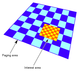
In one LOD, the blocks most likely accessed, according to the view and position of the viewer, are called the interest area of the LOD. It is these blocks that get paged in.
The interest area for an LOD whose resolution is based on range is bounded by the maximum range value for that LOD. The interest area is smaller for higher resolution LODs, larger for lower resolutions LODs. As a result, the memory requirements of ASD are reduced because not all LODs in an area are paged in: triangles closer to the viewer are paged in at a higher resolution LOD than those triangles further from the viewer, as shown in Figure 20-18.
Each square in Figure 20-18 holds the same amount of information: the large pages hold a large amount of low-resolution information while the small pages hold a small amount of high-resolution information.
If the observer does not make discontinuous jumps in location between 2 frames, you use an algorithm that anticipates what the viewer needs to see next based on the evaluation function. For example, if the evaluation function is based on distance, you would page blocks into memory in the direction you expect the viewer to go and release from memory those pages the viewer is leaving.
Preprocessing pages improves performance.
Determine the appropriate tiles size for each LOD based on the evaluation function.
Assign triangles in each LOD into tiles and store each tile in a paging unit, such as a file.
Assign a triangle to one tile only. Triangles with the same parent node must be assigned to the same tile.
Generate a set of fast-paging files for a specific set of paging areas.
When the application is run, it should anticipate the pages the viewer will need and then page them into memory from disk and preprocess them.
P aging in lower LOD pages before higher LOD pages ensures that a page at some level of LOD is always ready for the viewer. When you travel so fast through a surface that the higher resolution LODs do not have time to load, the surface has a lower resolution, which is what you would expect to see when traveling fast.
pfASD supports multi-resolution paging. The format of a paging file, where all of the geometries are in one tile, is described by the following structure:
int numfaces int numverts /* numfaces of the following */ int faceid1 /* structure of the face faceid1 */ pfASDFace face /* structure of the face faceid2 */ int faceid2 pfASDFace face ... /* numfaces of the following */ /* face bounding box of faceid */ pfBox box1 /* face bounding box of faceid2 */ pfBox box2 ... /* numverts of the following */ int vertid1 /* structure of vertex vertid1 */ pfASDVert vert int vertid2 /* structure of vertex vertid2 */ pfASDVert vert ... |
To calculate the paging area, use the following code:
page[0] = (int)(lods[i].switchin/tilesize[0]) + lookahead[0]; page[1] = (int)(lods[i].switchin/tilesize[1]) + lookahead[1]; |
lods[i] is the pfASDLODRange of LOD[i]. tilesize is the size of the tile in LOD[i]. lookahead is the number of extra tiles in one direction to page in to memory to overcome a paging delay
To process the paging tiles into a fast paging format, use pfdProcessASDTiles() in pfdProcASD.c. pfdProcessASDTiles() returns a new set of files as xxxx.asd. These files are paged in real-time.
For an example of writing a file, see pfdWriteFile() in libpfdu/pfdBuildASD.c.
