When you create a geometry, it has a specified size, location, and orientation, as defined in its own space. You can place such a geometry:
In relationship to other shapes in the same scene.
Into the coordinate system of the root node, known as world space.
This chapter describes how to perform these tasks in the following sections:
Geometries are often created in a local coordinate system, modeled at the origin. To place geometries in a scene, the geometry must be given positions in the scene, or world space. This transformation of location establishes a new local transformed coordinate system. OpenGL Performer allows you to specify these transformations in the scene graph to position geometries, as shown in Figure 9-1.
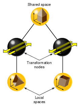
Because a scene graph can be very wide and very deep, containing thousands of shapes, transformation nodes are often stacked. The transformation node at the top of the branch concatenates the transformations of all the transformation nodes directly below it. Transformations, however, are not carried over from one branch to another. For example, in Figure 9-1, the transformation node in the left branch does not affect the shape in the right branch.
As transformation nodes are encountered in the traversal, they are post-multiplied: (Geometry x TransformB) x TransformA.
When you want to put all of the shapes in a scene graph into one space, you use multiple transformation nodes to translate the shapes into the coordinate system of the root node of the scene graph. The coordinate system of the root node is called world space.
Geometry space is the coordinate system in a subsection of a scene graph.
To put shapes together in a common space, or to reorient, reposition, or rescale a shape, you use one of two transformation nodes:
pfFCS—for dynamically transforming geometries, in concert with pfFlux, to create movement.
pfDCS—for transformation values that do change.
pfSCS—for transformation values that do not change once they are set.
If you have shapes, like a rock, that do not move in a scene, use a pfSCS node to transform them. If a shape, such as a car, does move in a scene, use a pfDCS node to transform it.
| Tip: Because pfDCS nodes require more processing, make as few pfDCS nodes as possible. |
Each of the transformation nodes provide methods to scale, rotate, or translate a shape to the coordinate system of the transformation's parent node.
For a given transformation node, multiple transformations are applied in the following order: scale, rotate, translate.
The order in which you perform transformations can affect the final result. Consider, for example, translating and rotating an image. If you perform the transformations in this order, you end up with a rotated model translated, for example, down the X-axis, as shown in Figure 9-2.
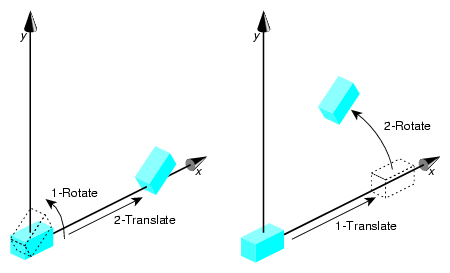
When you reverse the order of the transformations, the end result is different. Because the center of rotation is about the origin, the rotation transformation lifts the object above the X-axis.
pfFCS is used as a parent node to a pfGeode, containing pfGeoSets or pfGeoArrays. pfFCS can place the transformation matrix in a pfFlux object. pfFlux is a container for holding dynamic data, and stores the output data of a pfEngine. A pfEngine then can update the transformation matrix held in the pfFlux object, which transforms the child node of the pfFCS, as shown in Figure 9-3.
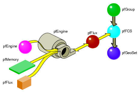
In this figure, the pfEngine performs calculations on the data input from the pfMemory nodes and sends the results to the pfFlux node. The pfFlux node contains the matrix for the pfFCS node. The output data from the pfEngine, manipulates the matrix in pfFlux, which, in turn, manipulates the pfGeode geometry, which is wrapped in the pfFCS node. In this way, the pfEngine animates the pfGeode geometry.
For more information about pfFlux, pfEngine, and pfFCS nodes, see Chapter 14, “Dynamic Data ,” in the OpenGL Performer Programming Guide.
Example 9-1 shows an implementation of pfFCS, pfFlux, and pfEngine.
Example 9-1. Connecting Engines and Fluxes
// create the nodes pfFlux *myData1 = new pfFlux(100 * sizeof(pfVec3)); pfFlux *myData2 = new pfFlux(100 * sizeof(pfVec3)); pfEngine *myEngine = new pfEngine(PFENG_SUM); pfFlux *engineOutput = new pfFlux(100 * sizeof(pfVec3)); pfFCS myFCS = new pfFCS(); pfGeode myGeode = new pfGeode(); // initialize and populate the flux nodes myData1->init(); myData2->init(); // attach the pfFlux nodes as the source of the pfEngine myEngine->setSrc(0, myData1, 0, 3); myEngine->setSrc(0, myData12, 0, 3); // attach a pfFlux to the output of the pfEngine myEngine->setDst(engineOutput, 0, 3); myEngine->iterations(100, 3); // connect the pfFlux output node to the scenegraph myFCS->setFlux(engineOutput); // attach child geometry to be tranformed by the FCS myFCS->addChild(myGeode); ... // compute the data in the source pfFluxes to the engine float *current = (float *)myData1->getWritableData(); ... // compute data myData1->writeComplete(); |
You use DCS nodes to transform shapes when the transformations might change over time. For example, a rotating wheel changes its rotational angle over time.
To set the orientation, rotation, and scaling of the shape in the transformation's parent node, use the following methods, respectively:
void pfDCSTrans(pfDCS *dcs, float x, float y, float z); void pfDCSRot(pfDCS *dcs, float h, float p, float r); void pfDCSScale(pfDCS *dcs, float s); |
pfDCS includes overwritten forms of these methods so that you can express the arguments in different units.
pfDCSScale() scales all three axes the same amount.
All of the transformation values only take effect when the DCS node is traversed by a DRAW action.
An alternative to specifying translation and rotation values separately is using the pfDCSCoord() method, as follows:
void pfDCSCoord(pfDCS *dcs, pfCoord *coord) |
This call is equivalent to:
pfDCSTrans(dcs, coord.xyz[PF_X], coord.xyz[PF_Y], coord.xyz[PF_Z]); pfDCSRot(dcs, coord.hpr[PF_H], coord.hpr[PF_P], coord.hpr[PF_R]); |
By default, OpenGL Performer recalculates bounding volumes every time a transformation node is updated. To reduce the number of times a bounding volume is recalculated requires special knowledge of your visualization. For example, if your visualization is that of a solar system, every time a planet moves around the sun, its bounding volume is recalculated. Instead, by knowing the dimensions of your solar system model, you can set the bounding volume large enough so that it encompasses the motion of the planet and therefore never needs to be recalculated. Set the bounding box as high in the scene graph as you can at the transform node itself.
To turn off bounding volume recalculation, use the PFBOUND_STATIC token as the value for mode in the following pfNode method:
void pfNodeBSphere(pfNode *node, pfSphere *sph, int mode); |
node, in this case, is the DCS node.
sph is the bounding sphere whose size you set so that recalculating the bounding sphere is unnecessary. If you set sph to NULL, the bounding sphere is automatically calculated.
OpenGL Performer makes internal optimizations based on knowing the matrix type, and based on calls, such as pfDCSTrans() and pfDCSRot(). Otherwise you can specify the matrix type using pfDCSMatType().
An SCS node contains a transformation matrix that concatenates matrices for translating, rotating, and scaling a shape. The value of using a matrix is its speed of computation. The transformation values in a SCS node, however, cannot be changed once the SCS node is created.
To create an SCS node, use the following member function:
pfSCS *pfNewSCS(pfMatrix mat); |
mat is the concatenation of the matrices for translating, rotating, and scaling a shape.
To set the transformation values in a SCS node:
Use pfMatrix pfMake..Mat() methods to define the first transformation matrix value.
Use the resulting matrix as the argument for creating the SCS node.
Use pfMatrix pfPre..Mat() methods to define the remaining transformation matrix values.

Note: Alternatively, you can use only pfMatrix pfMake..Mat() methods to define the transformations and then use pfMultMat() iteratively to multiply the three transformation matrices to yield the argument for pfNewSCS().
To set the orientation, rotation, and the scaling transformation values, use the following pfMatrix methods, respectively:
void pfMakeTransMat(pfMatrix dst, float x, float y, float z);
void pfMakeRotMat(pfMatrix dst, float degrees, float x, float y,
    float z);
void pfMakeScaleMat(pfMatrix dst, float x, float y, float z);
|
dst in each method is the output transformation matrix for the function.
You can concatenate transformation matrices by setting up one transformation method and then using one of the following pfMatrix methods:
void   pfPreTransMat(pfMatrix dst, float x, float y, float z,
    pfMatrix m);
void   pfPreRotMat(pfMatrix dst, float degrees, float x, float y,     float z, pfMatrix m);
void   pfPreScaleMat(pfMatrix dst, float x, float y, float z,
    pfMatrix m);
|
Each of these methods performs the matrix math to concatenate one matrix transformation with another before the SCS node is traversed by an action.
For example, to rotate a shape and then translate it, use the following code:
pfMakeRotMat(mat, degrees, x, y, z); pfPreTransMat(mat, x1, y1, z1, mat); |
When you have multiple SCS transformations in a branch of a hierarchy, you can optimize the performance of an application by pre-calculating their concatenation. To do so, use the following pfNode methods:
int pfFlatten(pfNode *node, int mode); pfNode *pfdCleanTree(pfNode *node, pfuTravFuncType func); |
The mode argument in pfFlatten is currently ignored and should be 0.
pfFlatten precalculates at initialization the result of all transformation matrices in a branch of a node hierarchy. If a geometry is referenced by more than one SCS node, pfFlatten does the following:
Clones the geometry for each SCS node.
Calculates the transformed locations of each SCS node.
Changes the SCS matrix values to an identity matrix.
Figure 9-4 shows this process.
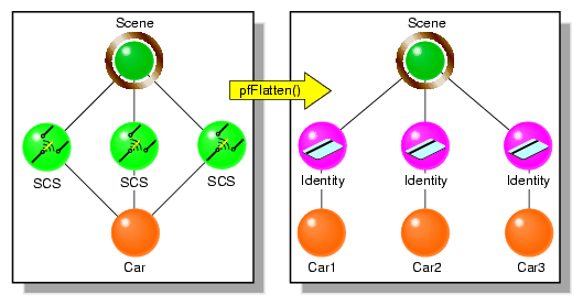
In Figure 9-4, pfFlatten calculates the transformation of the car into three locations; those locations are stored in the Scene node. As a result, three matrix calculations are reduced to matrix result.
You identify the node in which to store the matrix concatenation in the pfFlatten method. This node is generally the node at the top of a branch.
| Note: If a DCS node is encountered under the SCS node, an SCS node is inserted above the DCS node. |
Flattening can substantially improve performance, especially when many pfSCS nodes are parents for a relatively small number of geometries. However, as Figure 9-4 shows, pfFlatten can also increase the size of the database. To remedy that problem, you use pfdCleanTree, as described in “pfdCleanTree”.
Flattening also increases the ability of OpenGL Performer to sort the database by mode, often a major performance enhancement, because sorting does not cross transformation boundaries.
The SCS nodes containing identity matrices as a result of pfFlatten() serve no function. To remove these nodes from the database, as shown in Figure 9-5, use pfdCleanTree using NULL as the value of func.
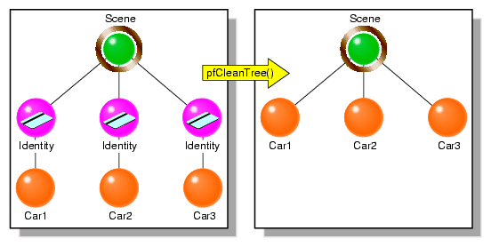
When func is NULL, pfdCleanTree performs as follows:
Converts pfSCS nodes with identity matrices into pfGroup nodes.
Removes any pfGroup nodes with zero or one child.
One exception is a pfSwitch node with one child, which is not eliminated.
You only call pfdCleanTree after calling pfFlatten.
Optionally, you can supply your own function to change the behavior of pfdCleanTree. Whatever the function, if func returns TRUE, the current node is eliminated; if func returns FALSE, the current node is retained.