This chapter explains how to combine video frame information and computer-generated graphics on the Indigo2 workstation. Use the VL and the OCTANE Digital Video board to perform three types of blending:
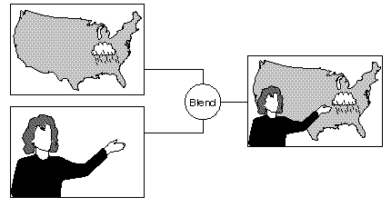
Chroma keying: overlaying one image on another by choosing a key color. For example, if chroma keying is set to blue, image A might show through image B everywhere the color blue appears in image B. A common example is the TV weather reporter standing in front of the satellite weather map. The weather reporter, wearing any color but blue, stands in front of a blue background; keying on blue shows the satellite picture everywhere blue appears. Because there is no blue on the weatherperson, he or she appears to be standing in front of the weather map.
Luma keying: overlaying one image on another by choosing a level of luminance. For example, to overlay bright text (such as a caption) on video, a graphics source is created with the text on a dark background. The video source is made to show through the dark areas of the graphics; the bright text remains on top of the video.
Transitions: fades, tiles, and wipes, such as single, double, or corner wipes, for which you can set the angle or center.
The choice “Blend/Wipe Node” in the Pro menu of the panel vcp, a graphical user interface for VL and the OCTANE Digital Video board, provides convenient access to blending, keying, and transition controls.
This chapter explains
Blending takes place in the VL's internal blender node, which mixes the foreground and background video signals by applying a blend function to the foreground and background pixels.
The blender node is supplied by four independent inputs:
pixel from a foreground source (A)
the alpha value for source A
pixel from a background source (B)
the alpha value for source B
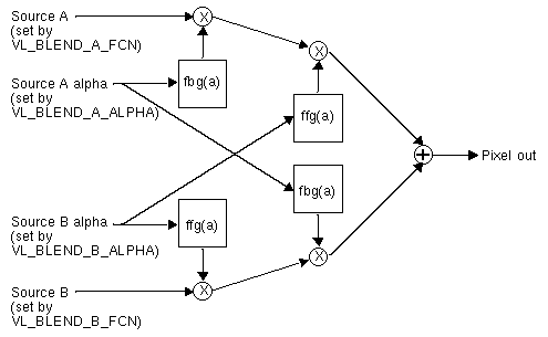
Figure 7-1 diagrams the blender node.
The blender node has four multiplier stages, indicated by ⊗ in Figure 7-1, and one adder stage, indicated by ⊕. The values in the four multiplier stages are based on the blending functions selected and on the input normalization controls.
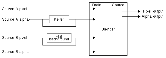
Of the four inputs shown in Figure 7-1, two have alternate sources. The OCTANE Digital Video keyer is hard-wired to alpha source A and the flat-background generator is hard-wired to pixel source B, as diagrammed in Figure 7-2.
The keyer produces an alpha stream from a pixel stream, generating a key for each pixel in each source node. It is described in detail in “The Keyer” later in this chapter. The flat-background generator sets the background pixel stream (source B pixel) to a default background color or to another color.
| Note: When a screen source is designated as source A alpha, the blender can extract alpha from it, because a screen source “contains” alpha. Otherwise, any other pixel stream is 4:2:2. If a source other than screen is designated as source A alpha, the blender uses the Y value as alpha and discards the U and V values. |
The rest of this section explains
setting up the blender node
setting normalization
setting and turning off flat background
adding shadows
Figure 7-3 diagrams setting up the blender node.
The blender node is created with the vlGetNode() function. The code fragment in Example 7-1 sets up source, drain, and blender nodes. Notice that the drain nodes are set up before the source nodes.
Example 7-1. Setting Up Source, Drain, and Blender Nodes
/* variable definitions */
{
 VLServer vlSvr;
 VLPath path;
 VLNode drn_scr, drn_vid, src_scr, src_vid, blend_node;
}

/* Open a video device */
vlSvr = vlOpenVideo(“”);

/* Set up drain nodes on the screen and video */
drn_scr = vlGetNode(vlSvr, VL_DRN, VL_SCREEN, VL_ANY);
drn_vid = vlGetNode(vlSvr, VL_DRN, VL_VIDEO, VL_ANY);

/* Set up source nodes on the screen and video */
src_scr = vlGetNode(vlSvr, VL_SRC, VL_SCREEN, VL_ANY);
src_vid = vlGetNode(vlSvr, VL_SRC, VL_VIDEO, VL_ANY);

/* Set up internal blending node */
blend_node = vlGetNode(vlSvr, VL_INTERNAL, VL_BLENDER,
                       VL_ANY);
|
Table 7-1 summarizes the generic VL blending controls. For all these controls, access is GST:
G: The value can be retrieved through vlGetControl().
S: The value can be set through vlSetControl() while the path is not transferring.
T: The value can be set through vlSetControl() while the path is transferring
Table 7-1. General Blender Controls
Some of the operations are not very useful, for example VL_BLDFCN_ONE, VL_BLDFCN_ONE adds the two images; the hardware clips pixels that are too bright.
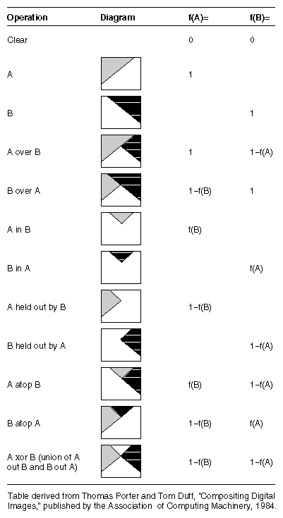
You can compose the 12 standard Porter-Duff operations by combining the values of VL_BLEND_A_FCN and VL_BLEND_B_FCN. Figure 7-4 gives some examples of compositing, assuming normalized inputs. Normalized background pixels for a frame are premultiplied by their corresponding alphas before they are blended.
Table 7-2 shows the choices for the two blend functions A and B, which correspond exactly.
Table 7-2. Choices for Blend Functions A and B
Blend Function A | Blend Function B |
|---|---|
f(A) = 0.0 | f(B) = 0.0 |
f(A) = 1.0 | f(B) = 1.0 |
f(A) = f(A) | f(B) = f(B) |
f(A) = 1 - f(A) | f(B) = 1 - f(B) |
The value 0.0 sets the display to black (cut the foreground or background value); the value 1.0 sets the display to white (pass the foreground or background value):
If both foreground and background are set to 0.0, the result is black (both foreground and background are cut).
If foreground is set to 0.0 and background is set to 1.0, foreground is cut (ignored) and background is passed (displayed).
If foreground is set to 1.0 and background is set to 1-f(A), background obscures and overlaps foreground, resulting in compositing.
Normally, chroma is multiplied (scaled) by the selected alpha. For example, the value on source A can be multiplied by its own alpha value or that from source B. In a normal blend, f(A), the incoming alpha of source A is applied to the value for A. In the inverse of this blend, f(A)=1-f(A), the region that was considered opaque (turned off), that is, outside the volume defined for keying, is applied to source A.
In another way of blending, the alpha from source B can be applied to the component represented by source A. In the inverse of this blend, f(A)=1-f(B), the region that was turned off for source B is applied to source A.
For screen inputs, set VL_BLEND_B_NORMALIZE to FALSE if the keyer mode is set to pass-through (VL_KEYERMODE_NONE), because the alpha has been applied once by the graphics in most cases. In other words, set VL_BLEND_B_NORMALIZE to FALSE if it is following another blender.
For foreground-to-background wipes, background alpha is set to a constant value of 1.0, so that the background shows through the foreground.
For the OCTANE Digital Video option, pixel source B is normally a flat background, supplied by a flat-background generator on this wire (see Figure 7-2). However, you can use device-dependent controls to set the background as desired:
VL_MGV_BLEND_B_FLAT (default: off)
When this control is TRUE (on), the background pixel source is used for pixel timing only and live video from pixel source B goes to the blender.
When this control is off, you can set three controls listed below to values of your choosing for the background. The default value for the background is gray.

Note: Set this value before the background is turned on if you wish to avoid a flash. VL_MGV_BLEND_B_Y (default: 128)
The legal range of Y is 16 to 235.
VL_MGV_BLEND_B_U (default: 128 (50% gray))
The legal range of U is 16 to 240.
VL_MGV_BLEND_B_V (default: 128)
The legal range of V is 16 to 240.
The software does not prevent you from using values outside of the range (1-254):
The values of 1 and 254 are superblack and superwhite.
The setting Y=235, U=128, V=128 is 100% white.
The shadow hardware adds back the Y information from the area that was cut by the keyer. If a shadow exists in the cut area, the effect is to dim the pixels in the area of that shadow in the replaced background.
Use these device-dependent controls to set the shadow values:
-
Set this control to TRUE to activate the shadow hardware.
VL_MGV_BLEND_SHADOW_GAIN
The range for this control is 0.0 to 3.0, which shifts the value.
Use this control and the next one to make the shadow darker or lighter than the “real” shadow you see in the input video.

Note: Darkening a very light shadow can result in noise. VL_MGV_BLEND_SHADOW_OFFSET
The range for this control is 0 to 255, which is added to the value.
Shadows that are very dark may be hard to key. These registers affect only the background pixels; foreground areas are passed through by the blender. Tune the values for the best effect.
For each kind of keying—luma keying, chroma keying, and transitions—further VL controls enable you to specify the properties of the blend.
The values for the OCTANE Digital Video “master” keyer control, VL_MGV_KEYER_MODE, determine the type of keying performed:
luma keying: VL_MGV_KEYERMODE_LUMA
chroma keying: VL_MGV_KEYERMODE_CHROMA
transitions, that is, fades, tiles, or wipes: VL_MGV_KEYERMODE_SPATIAL
For example, the following fragment specifies a fade:
VLControlType val;
val.intVal = VL_MGV_WIPETYPE_FADE;
vlSetControl(vlSvr, vlPath, blend_node, VL_MGV_WIPE_TYPE,
             &val);
|
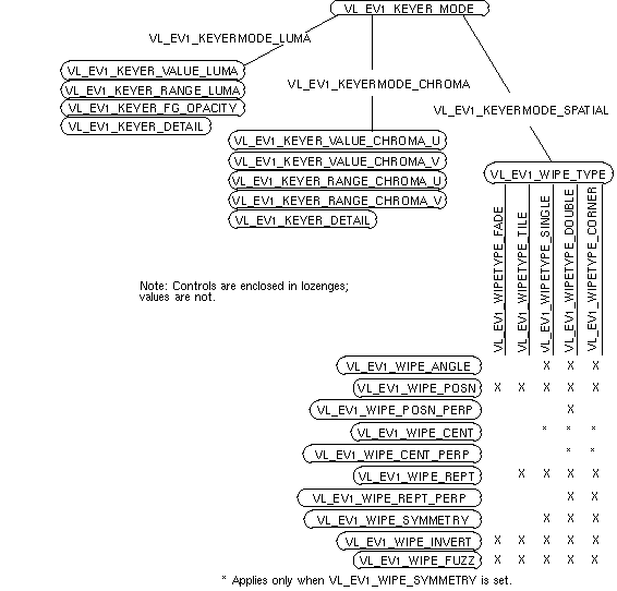
Each type of keying is explained separately in this section. Figure 7-5 shows the relationships between the OCTANE Digital Video board keying and wipe controls.
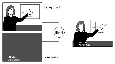
Luma keying is typically used to overlay a fixed image on video, such as the name and title of an individual being interviewed, a cable channel's logo, or a symbol that denotes an ongoing news story during a newscast. Figure 7-6 illustrates the results of luma keying.
The OCTANE Digital Video luma keying controls are summarized in Table 7-3. For each, the type is intVal and access is GST. The default value is persistent: it is initially obtained from the defaults file, but is never reset. Many controls available through the video control panel vcp (for example, the default video input) fall into this category. For this value, changes made by vlSetControl() are persistent across paths, even if the node goes into an unused state.
Table 7-3. OCTANE Digital Video Luma Keying Controls
Control | Range | Sets |
|---|---|---|
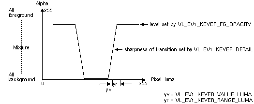
VL_MGV_KEYER_VALUE_LUMA | (0,255) | Central luma value. This control sets the luma value at which the background shows through the foreground. |
VL_MGV_KEYER_RANGE_LUMA | (0,255) | One-sided range of the center value. This control determines the range of luma values where the background shows through the foreground. |
VL_MGV_KEYER_FG_OPACITY | (0,255) | Opacity of the foreground, thus limiting the value of foreground alpha at any point. |
VL_MGV_KEYER_DETAIL, VL_MGV_KEYER_SHARPNESS, VL_MGV_KEYER_FUZZ | (-8,7) | Sharpness of transition between foreground and background allowing blurring of edges. The value -8 yields the most gradual transition, +7 the sharpest. |
Figure 7-7 diagrams the relationships between these controls.
Chroma keying overlays one image on another based on the color value. Figure 7-8 illustrates an example of chroma keying.
Table 7-4 summarizes the controls for OCTANE Digital Video chroma keying and gives their ranges. For each, default is persistent, access is GST, and type is intVal.
Table 7-4. OCTANE Digital Video Chroma Keying Controls
Control | Range | Sets |
|---|---|---|
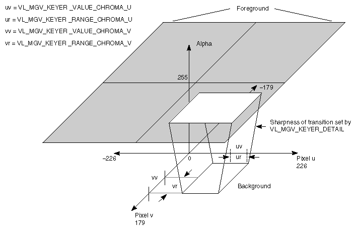
VL_MGV_KEYER_VALUE_CHROMA_U | (-226,226) | Central U value at which the background shows through the foreground. |
VL_MGV_KEYER_RANGE_CHROMA_U | (0,452) | One-sided range of U where the background shows through the foreground. |
VL_MGV_KEYER_VALUE_CHROMA_V | (-179,179) | Central V value at which the background shows through the foreground. |
VL_MGV_KEYER_RANGE_CHROMA_V | (0,358) | One-sided range of V where the background shows through the foreground. |
VL_MGV_KEYER_DETAIL, VL_MGV_KEYER_SHARPNESS, VL_MGV_KEYER_FUZZ | (-8,7) | Sharpness of transition between foreground and background |
| Note: VL_MGV_KEYER_FG_OPACITY has no effect on OCTANE Digital Video in chroma key mode. |
Figure 7-9 diagrams the relationships between these controls.
The values used with the control VL_MGV_WIPE_TYPE determine the type of blending performed:
from all-foreground to all-background: VL_MGV_WIPETYPE_FADE
from all-foreground to all-background by randomly tiling screen with rectangles of a specified size: VL_MGV_WIPETYPE_TILE
wipe to cross the screen as a vertical, diagonal, or horizontal “front,” with a specified angle: VL_MGV_WIPETYPE_SINGLE
wipe in two orthogonal directions simultaneously (two single wipes at the same time): VL_MGV_WIPETYPE_DOUBLE
wipe in two orthogonal directions, with the perpendicular position locked to the normal, or in-line position: VL_MGV_WIPETYPE_CORNER
For example, the following fragment specifies that a fade is to be performed:
VLControlType val;
val.intVal = VL_MGV_WIPETYPE_FADE;
vlSetControl(vlSvr, vlPath, blend_node, VL_MGV_WIPE_TYPE,
             &val);
|
Fades, tiles, and wipes go from all-foreground (VL_MGV_WIPE_POSN=0) to all-background (VL_MGV_WIPE_POSN=1000), unless VL_MGV_WIPE_INVERT control is set, in which case they go from all-background (VL_MGV_WIPE_POSN = 0) to all-foreground (VL_MGV_WIPE_POSN = 1000).
Table 7-5 summarizes controls common to all wipe types.
Table 7-5. Controls for Fades, Tiles, and Wipes
Control | Values | Sets |
|---|---|---|
VL_MGV_WIPE_POSN | Numerator (0,1000) | Amount of progress of wipe, from none (numerator = 0) to full (numerator = 1000). |
VL_MGV_WIPE_REPT | (0,15) | Number of repetitions of pattern in direction of wipe, usually
louvers on single, corner, or double wipe, and length of one
side of rectangles for a tile wipe. |
VL_MGV_WIPE_INVERT | (0,1) | Reversal of foreground and background regions of a wipe. When set to 0, wipes proceed from foreground (position = minimum) to background (position = maximum). When set to 1, wipes proceed from background (position = minimum) to foreground (position = maximum). This value is buffered (does not go into effect) until another blending control is set. |
Table 7-6 summarizes the controls specific to wipes or that work differently for wipes. For each, access is GST and the default is persistent, except VL_MGV_WIPE_SYMMETRY and VL_MGV_WIPE_INVERT, for which it is FALSE. Some of these controls work in conjunction with each other.
Table 7-6. OCTANE Digital Video Controls Specific to Wipes
Control | Values | Sets |
|---|---|---|
VL_MGV_WIPE_DIRECTION | VL_MGV_WIPEANGLE_E | Wipe vector direction, that is, the direction in which the wipe appears to be proceeding as its position increases. Note: VL_MGV_WIPEANGLE_N and VL_MGV_WIPEANGLE_S do not work for the wipe types VL_MGV_WIPETYPE_DOUBLE and VL_MGV_WIPETYPE_CORNER
|
VL_MGV_WIPE_FUZZ | (-8,7) | Sharpness of wipe transition band. As for VL_MGV_KEYER_DETAIL, -8 is most gradual, +7 is sharpest. |
VL_MGV_WIPE_SYMMETRY | (0,1) | Wipe symmetry (on or off) so that wipe proceeds in both directions at once from the center line. Effect depends on type of wipe: no effect for fades or tiling; enables VL_MGV_WIPE_CENT for single, double, and corner wipes; enables VL_MGV_WIPE_CENT_PERP control for double and corner wipes. |
VL_MGV_WIPE_POSN_PERP | numerator (0,1000) | Amount of progress of wipe, from none (numerator = 0) to full (numerator = 1000), along a direction perpendicular to normal wipe position VL_MGV_WIPE_POSN. |
VL_MGV_WIPE_CENT | numerator (0,1000) | Offset that is center of a symmetrical wipe along wipe position. 0 means center is where VL_MGV_WIPE_POSN is 0, and 1000 means center is where VL_MGV_WIPE_POSN is 1000. For this control to work for single, double, and corner wipes, VL_MGV_WIPE_SYMMETRY must be on. |
VL_MGV_WIPE_CENT_PERP | numerator (0,1000) | Offset that is center of a symmetrical wipe along a perpendicular wipe position. 0 means center is where VL_WIPE_POSN_PERP is 0, and 1000 means center is where VL_WIPE_POSN_PERP is 1000. VL_WIPE_SYMMETRY must be on for this control to work for double and corner wipes. |
VL_MGV_WIPE_REPT_PERP | (0,15) | Number of repetitions perpendicular to wipe direction for single, double, and corner wipes, and length of other side of rectangles for tile wipe.
|
The role of the keyer is to take a pixel stream and produce an alpha stream. It generates a key for each pixel in each source node:
The keyer determines the alpha value (opacity) of a pixel and sets a value for it ranging from 0 (completely transparent) to 1 (completely opaque). This alpha value can be used downstream for further layering operations. The program simpleblend.c illustrates this procedure; it is included in the software and described at the end of this chapter.
The control VL_MGV_BLEND_H_FILT is a horizontal smoothing filter that, if set to TRUE, filters pixel information before the alpha extraction. It smooths the alpha output of the key generator, softening the edges of the image.
Figure 7-10 shows the relationships between value, range, and detail (transition) for a single channel (for example, A).
This section explains two example programs from /usr/share/src/dmedia/video/vl:
simpleblend.c
simplewipe.c
Because the programs are lengthy, they are not duplicated here. Look at the source code in a separate window, or print them out to look at while you read their descriptions.
| Caution: To simplify the code, these examples do not check returns. However, you should always check returns. |
simpleblend.c blends video with graphics and outputs it to both a graphics window and video out. The program
constrains the window's aspect ratio
checks that the device the user requested is in the device list
sets up a path between the source (screen) and the drain (video)
adds video source and a screen drain nodes to create the blend
sets the keyer mode, keyer source, and blend controls
displays the drain window and sets the video to appear in it
specifies appropriate event handling
starts data transfer
specifies that video is updated if the user changes the size of the window
Like simpleblend.c, simplewipe.c blends video with graphics and outputs it to a graphics window and video out. When the user presses the w key, it executes a wipe.
Specifically, in addition to doing everything that simpleblend.c does, simplewipe.c
sets up blend parameters (VL_WIPE_TYPE, VL_WIPE_ANGLE or VL_WIPE_DIRECTION, VL_WIPE_CENT, VL_WIPE_REPT)
calls a loop that sets the keyer mode to spatial and sets the position in the loop; doswitchloop() and dowipe() execute the loop
checks for the w key and calls dowipe(), which in turn calls doswitchloop()
