This chapter provides information on installing the SGI Origin 300 server on a table top or in an SGI 19-inch rack. This chapter also includes instructions on how to remove the server from the rack. Specifically, the following topics are covered:
“Installing the Server in an SGI Rack”

Note: The server rackmounting kit also enables the server to be mounted in an industry-standard 19-inch rack. “Removing the Server from an SGI Rack”

Warning: Employ a minimum of two people to lift the server off the shipping pallet, move the server from one location to another, and install the server in a rack or serious injury to personnel could occur. 
Warning: Use the following guidelines to prevent the rack from toppling over or serious injury to personnel and/or damage to equipment could occur.
Use the following guidelines to prevent the rack from toppling over:
Make sure that only one Origin 300 server is extended out of the rack at one time.
Install all equipment in the lowest available position in the rack.
Ensure that the tip tray is bolted to the front of the rack.
Inspect the packaging container for evidence of mishandling during transit. If the packaging container is damaged, photograph it for reference. After you remove the contents, keep the damaged container and the packing materials.
Remove the server from the packaging container and ensure that all accessories are included. Inspect the server and accessories for damage. If the contents appear damaged, file a damage claim with the carrier immediately. In addition, notify your local Customer Support Center (CSC) for any missing, incorrect, or damaged items.
CSC contact information is provided at the following URL: http://www.sgi.com/support/supportcenters.html
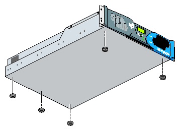
If you choose to operate your server on a table top, you need to install five self-adhesive feet that are supplied with the server. Follow these steps to install the feet:
Place the server upside down on a flat, stable surface.
Peel off the protective film from the feet and place them on the five circular marks as shown in Figure 2-1.

Note: If you mount the server in a rack at a later date, you will need to remove the feet.
The rackmount instructions include the following topics:
Table 2-1 specifies the space requirements for the SGI Origin 300 server when it is installed in a 19-inch rack.
Table 2-1. SGI Origin 300 Space Requirements
Height | 3.46 inches (8.79 cm) |
Width | 19.0 inches (48.3 cm) |
Depth | 27.0 inches (68.6 cm) |
Weight | 36.0 lbs (16.4 kg) |
Required front clearance for server | 8.25 inches (20.96 cm) |
Required rear clearance for server | 10.00 inches (25.40 cm) |
Required side clearance for server | 6.00 inches (15.24 cm) (right side) |
Required front clearance for rack | 36 inches (91 cm) |
Required rear clearance for rack | 36 inches (91 cm) |
Table 2-2 lists the hardware that you will use to mount the SGI Origin 300 server in a 19-inch rack.
Table 2-2. Rackmounting Hardware
Hardware Type | Qty | Usage |
|---|---|---|
Slide-rail assembly (includes chassis rail) | 2 | Allows the server to slide in and out of rack. |
2” rear mounting bracket | 2 | Mounts the slide rails to the rear rack rails. |
10-24 x 1/4” Phillips screw | 10 | Secures the chassis rails to the server. |
10-32 x 1/2” Phillips screw | 8 | Secures the slide rails to the rack rails. |
10-32 x 1/2” Phillips screw | 4 | Secures the slide rails to their mounting brackets. |
10-32 clipnut | 2 | Provides a threaded hole for fastening the server front panel to the rack rails. |
10-32 x 1/2” Phillips screw | 2 | Fastens the server front panel to the clipnut. |
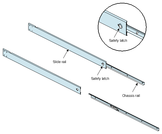
The slide-rail assembly consists of a chassis rail and a slide rail. You need to remove the chassis rail from the slide rail so that you can install a mounting bracket to the slide rail and attach the chassis rail to the server (refer to“Preparing the Server”). Follow these steps to remove the chassis rail from the slide rail:
Remove the two slide-rail assemblies and the rear mounting brackets from the shipping container.
Extend each slide-rail assembly until the safety latch snaps into place.
Press the safety latch and remove the chassis rail from the slide rail, as shown in Figure 2-2.
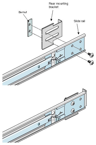
Place one of the mounting brackets on the back of the slide rail as shown in Figure 2-3. Adjust the position of the mounting bracket on the slide rail according to the depth of the rack.
Place a barnut next to the mounting bracket. Secure the mounting bracket to the slide rail by inserting two 10-32 x 1/2” screws through the assembly and into the barnut as shown in Figure 2-3.
Repeat Steps 4 and 5 to attach a mounting bracket to the other slide rail.
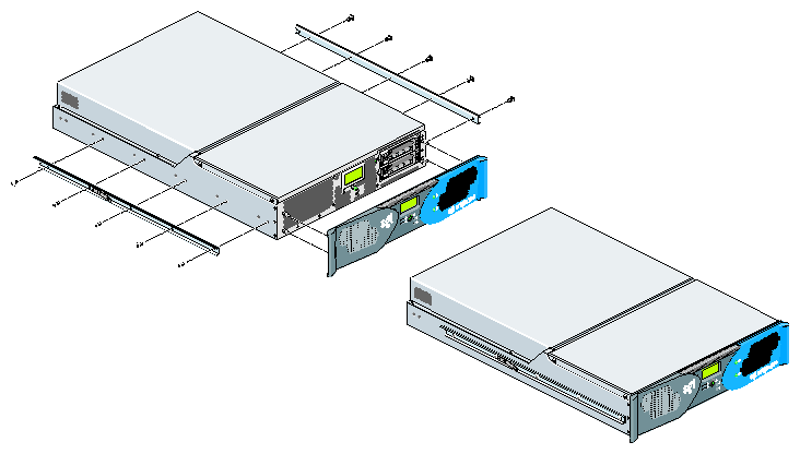
Follow these steps to attach the chassis rails to the server:
Place the server on a flat, stable surface.
Using five 10-24 x 1/4” screws, attach one of the chassis rails to the right side of the server chassis. Ensure that the rail is installed in the correct direction (refer to Figure 2-4).

Caution: Use only the 1/4-inch (0.64 cm) length screws. Longer screws damage internal components in the server. Repeat Step 2 to mount the second rail to the left side of the server chassis.
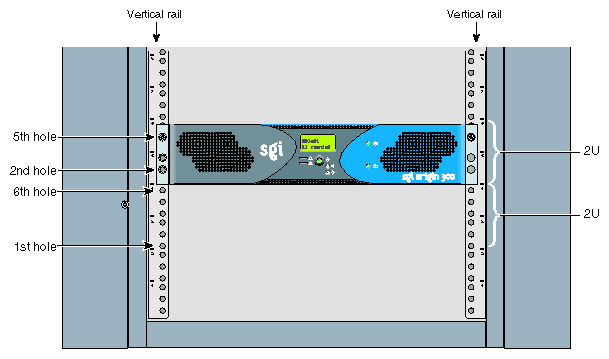
The server requires 2 units (U) of space within the rack. (1 unit is equivalent to 1.75 inches [44.5 cm]). To determine where you should install the slide rails in the rack, you must count mounting holes. Each U contains three mounting holes; therefore, in the 2U of space that the server occupies, there are six mounting holes. The bottom hole of the 2U space is hole 1. The top mounting hole in the 2U space is 6. Refer to Figure 2-5.
| Note: A server in the rack is identified by the lowest U number that it occupies. For example, in Figure 2-5 the server resides in U5 (the fifth unit within the rack). |
To determine how many mounting holes you must count, use the following formula: 3 x (the lowest U number that the server will occupy) - 2. For example, when you want to install the server in locations U9 and U10, count 25 mounting holes (3 x 9 - 2) starting from the bottom of the rack. The 25th hole is the first mounting hole of U9.
Follow these steps to attach the slide rail to the rack:
| Tip: The slide rails must be level in the rack. To ensure that you install the slide rails correctly, carefully count the mounting holes on all of the rack rails (two front rails and two rear rails). |
Locate eight 10-32 x 1/2” Phillips screws, eight shoulder washers, and four barnuts.
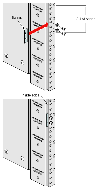
Place one of the barnuts inside the rack and align it with the second and third holes of the selected 2U of space (refer to Figure 2-6).

Note: The holes in the barnuts are not centered. The barnuts need to be placed in such a way that the holes are closest to the inside edge of the rack rails. Refer to Figure 2-6. Insert two screws with shoulder washers through the rack rail to hold the barnut in place. The screws should not be tightened at this point.
Repeat Steps 2 and 3 to install the remaining three barnuts on the other three rack rails (front and rear of rack).
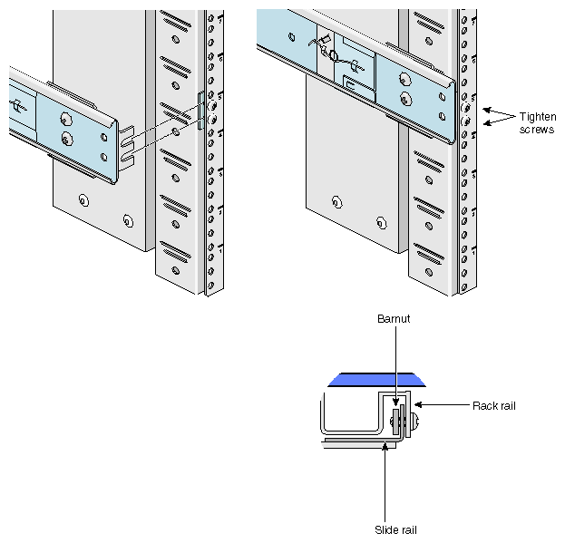
Insert the front and rear brackets of one of the slide rails between the rack rails and the barnuts, as shown in Figure 2-7.
Tighten the screws on the front- and rear-end of the rails. Do not tighten firmly at this point, because all screws will be firmly tightened once the server is installed in the rack.
Repeat Steps 5 and 6 to attach the second slide rail to the other side of the rack.
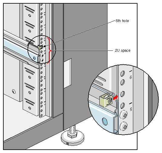
Clipnuts secure the servers to the rack. To install the clipnuts, slide the clipnuts over the fifth hole of the selected 2U of space on each of the front rails. Refer to Figure 2-8 for details.
Follow these steps to install the server in the rack.
| Note: Step 2 requires two people. |
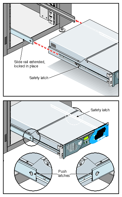
Fully extend the left and right slide rails from the rack until they lock into place.
With one person holding each side of the server, align the chassis rails of the server with the slide rails of the rack.
Slide the chassis rails into the slide rails until the chassis rails are stopped by the safety latches.
Press the safety latches on both sides of the server to fully seat the chassis rails into the slide rails (refer to Figure 2-9).
Firmly tighten all screws (the eight screws that secure the slide rails to the rack rails).
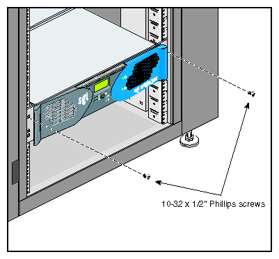
Secure the server to the rack by inserting a 10-32 x 1/2” Phillips screw in the top hole of each chassis ear (refer to Figure 2-10).
Once the server is installed in the rack, you can adjust the position of the server in the rack (upward and sideways). To adjust the position of the server, loosen the front mounting screws, adjust the server to the desired position, and then tighten the mounting screws.
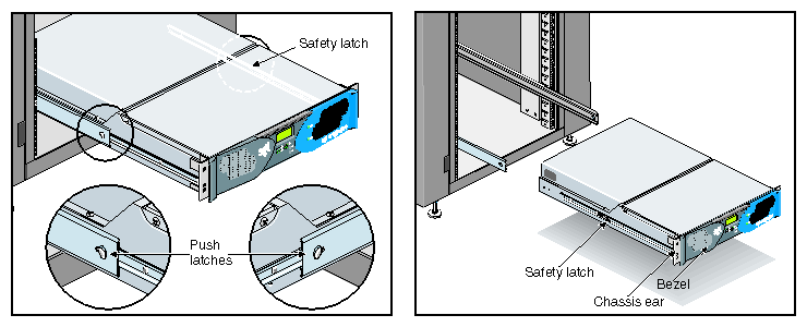
| Caution: Do not lift the server by its bezel; it is not designed to handle the weight of the server. Instead, use the chassis ears to move the server (refer to Figure 2-11). |
To remove the server from the rack, follow these steps:
Power off the server. For instructions on how to power off the server, refer to “Powering On and Off the Server” in Chapter 3.
Disconnect all of the cables at the rear of the server.

Warning: Components may be hot. To avoid injury, allow the components to cool for approximately 5 minutes before you proceed with these instructions. Remove the two screws that secure the server to the front rails of the rack.
Carefully pull the server from the rack until it is stopped by the safety latches.
With one person holding each side, release the safety latches on both sides of the server and pull the server out of the slide rail (refer to Figure 2-11).
Place the server on a flat, stable surface.
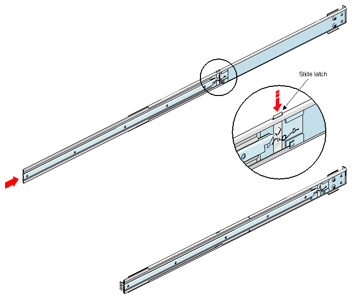
To slide the slide rails back into the rack, push down on the slide latches as shown in Figure 2-12.

Note: Before you can reinstall an Origin 300 server into the rack, fully extend the slide rails from the rack until they lock into place.
