This appendix provides detailed information about the following base components of the SGI Origin 300 system with NUMAlink module.
This appendix also includes detailed information about the following optional components:
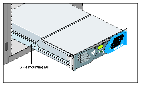
The SGI Origin 300 system with NUMAlink module supports two rack types: a short rack and a tall rack. Both rack types are industry-standard 19-inch racks, and they support two types of mounting rails that support the modules within the rack. For example, the Origin 300 base modules use slide mounting rails (refer to Figure A-1), which enable you to slide the base module from the rack to access PCI cards and memory.
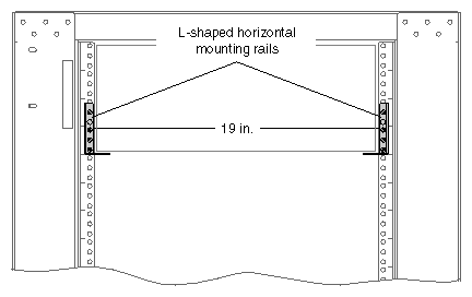
The NUMAlink module, PCI expansion module, and TP900 storage module are supported by two parallel L-shaped mounting rails within the rack (refer to Figure A-2).
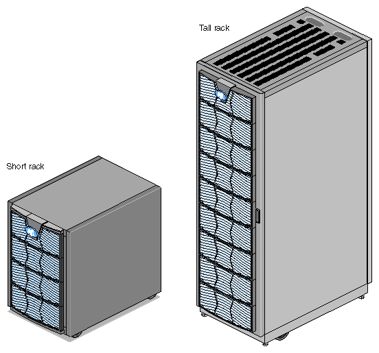
The SGI Origin 300 system can be housed in one short (17U) rack or one tall (39U) rack (refer to Figure A-3).
| Note: One U is 1.75 in. (4.45 cm). |
Table A-1 lists the specifications of the short rack.
Table A-1. Short-rack Specifications (with Skins)
Characteristic | Specification |
|---|---|
Height | 36.06 in. (916.00 mm) |
Width | 25.38 in. (645.00 mm) |
Depth | 40.63 in. (1032.00 mm) |
Weight (maximum) | 488 lb (221 kg) |
Shipping weight (maximum) | 563 lb (255 kg) |
Table A-2 lists the specifications of the tall rack.
Table A-2. Tall-rack Specifications
Characteristic | Specification |
|---|---|
Height | 75.82 in. (1925.83 mm) |
Width | 23.62 in. (599.95 mm) |
Depth | 41.25 in. (1048.00 mm) |
Weight (maximum) | 1,100 lb (499 kg) |
Shipping weight (maximum) | 1,281 lb (581 kg) |
Both rack types, as shown in Figure A-3, have front and rear doors that have keylocks to prevent unauthorized access of the system. The racks also have cable entry/exit areas at the bottom of the rack and cable management hardware in the rear of the racks.
Both rack types are mounted on four casters, two of which are swivel castors. The castors enable the racks to be rolled out of a shipping crate and to its placement at your site.
The base of the racks have seismic tie-down attachment points. The base of the tall rack also has leveling pads.
Table A-3 summarizes the general features of the SGI Origin 300 base module. Additional information is provided in the subsections that follow.
Table A-3. General Features of the SGI Origin 300 Base Module
Feature | Specification |
|---|---|
MIPS RISC processors | Two or four |
Memory | 512 MB to 4 GB |
Expansion slots | Two 32- or 64-bit (33- or 66-MHz) PCI slots |
Serial ports | Two DB-9 RS-232 or RS-422 |
Ethernet | One 10BaseT or 100BaseT |
SCSI channels (internal) | One Ultra3 SCSI, 160 MB/s |
SCSI channels (external) | One Ultra3 SCSI (VHDCI) |
3.5-in. drive bays | Two |
USB ports | Two |
RT interrupt input | One |
RT interrupt output | One |
L1 console port | One |
NUMAlink port | One (1.6 GB/s each direction) |
XIO port | One (800 MB/s each direction) This port is reserved for InfiniteReality graphics. |
Table A-4 shows the physical and environmental specifications for the SGI Origin 300 base module.
Table A-4. Physical and Environmental Specifications
Feature | Specification |
|---|---|
Height | 3.46 in. (8.80 cm) |
Width | 19.0 in. (48.3 cm) (front panel width) |
Depth | 26 in. (66 cm) (without bezel) |
Weight | 36.0 lb (16.4 kg) |
Temperature, | +5 ˚C (+41 ˚F) to +35 ˚C (+95 ˚F) (up to 1500 m / 5000 ft) |
Temperature, | -40 ˚C (-40 ˚F) to +60 ˚C (+140 ˚F) |
Humidity | 10% to 95% RH, noncondensing |
Altitude | Sea level to 40,000 ft (nonoperating) |
Noise | 50 dB(A) maximum |
Heat dissipation | 938 Btu/hr maximum |
Input power | 110/220 Vac autosensing (~275 W) |
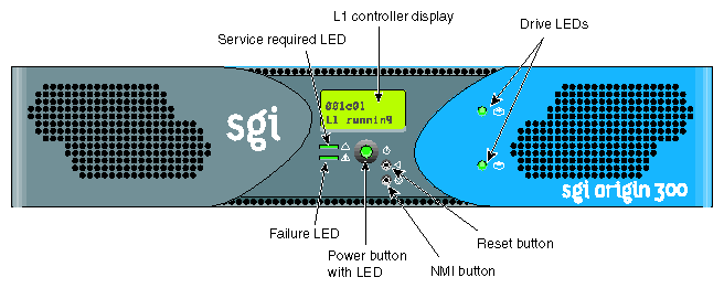
Figure A-4 illustrates the front controls and indicators of the SGI Origin 300 base module.
L1 controller display is a liquid crystal display (LCD) that displays status and error messages that the L1 controller generates.
Power button with LED enables you to manually power on and power off the Origin 300 base module. Alternatively, you can power on and off the base module at a system console. The LED illuminates green when the internal components are on.
Reset button resets the internal processors, ASICs, and memory.

Note: This reset causes memory loss. (Refer to the non-maskable interrupt [NMI] to perform a reset without losing memory.) Non-maskable interrupt (NMI) button resets the internal processors and ASICs without losing memory. Register data and memory are stored in a /var/adm/crash file.
Service required LED illuminates yellow to indicate that an item has failed or is not operating properly, but the base module is still operating.
Failure LED illuminates red to indicate that a failure has occurred and the base module is down.
Drive LEDs illuminate green to indicate drive activity.
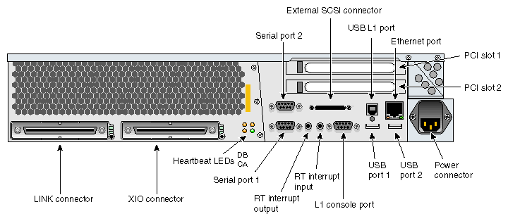
Figure A-5 illustrates the rear panel I/O ports and features of the SGI Origin 300 base module.
LINK connector (NUMAlink connector) connects the base module to a NUMAlink module. This connection is made with a NUMAlink 3 cable at 1.6 GB/s in each direction.
XIO connector connects to an InfiniteReality graphics module.
L1 console port (console and diagnostic port) connects the base module's L1 controller to a system console that runs the SGIconsole software.
USB L1 port (universal serial bus) connects the base module's L1 controller to an L2 controller.
PCI slots 1 and 2 house PCI cards. The two PCI 2.2-compliant slots are configured on one bus. The PCI bus supports both 32- and 64-bit modes at 33 or 66 MHz. Refer to the SGI Supportfolio Online home page at http://support.sgi.com for an updated list of supported PCI cards.
Serial ports 1 and 2 can be used as COM ports to connect modems or other serial devices.
USB ports 1 and 2 connect auxiliary equipment such as a keyboard or a mouse.
RT interrupt input and output (real-time interrupts) are used by the graphics cards to keep the graphics synchronized.
Ethernet port (autonegotiating 10BaseT or 100BaseT Ethernet port) connects the base module to an Ethernet network.
External SCSI connector (68-pin VHDCI external SCSI port) connects to SCSI devices (for example, TP900 storage module). Refer to the SGI Supportfolio Online home page at http://support.sgi.com for an updated list of supported SCSI devices.
Heartbeat LEDs (four, one for each processor) indicate processor activity.
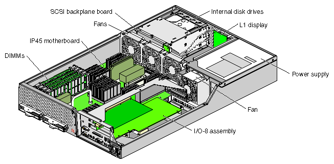
The internal components of the SGI Origin 300 base module are shown in Figure A-6 and described in the following subsections:
The IP45 motherboard houses the following components:
Two or four MIPS RISC processors (2-MB L2 cache per processor).
Four dual-inline memory module (DIMM) slots that are organized as two banks of memory per two DIMM slots (four banks total), and configurable from 512 MB to 4 GB of main memory. Refer to “Dual-inline Memory Modules (DIMMs)” for more information on DIMMs.
Bedrock ASIC (or hub ASIC) that enables communication between the processors, memory, and I/O devices.
Xbridge ASIC that is the interface between the Bedrock ASIC and the PCI slots.
Serial ID EEPROM that contains component information.
L1 controller logic that monitors and controls the environment of the base module (for example, fan speed, operating temperature, and system LEDs).
VRMs that convert the incoming voltages to the voltage levels required by the internal components.
Light-emitting diodes (LEDs) that provide information about the NUMAlink port and the processors:
Two NUMAlink LEDs, controlled by the L1 controller.
Four heartbeat LEDs (one for each processor), controlled by the Bedrock ASIC.
Ports that provide connection to external components.
Each SGI Origin 300 base module has from 512 MB to 4 GB of local memory, which includes main memory and directory memory for cache coherence.
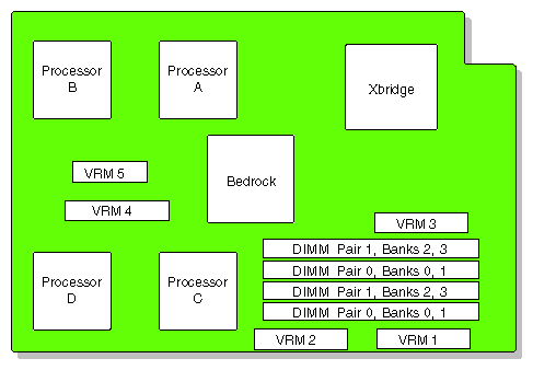
Local memory can consist of two to four banks, which are referred to as banks 0, 1, 2, and 3. The four banks are arranged as two DIMM pairs; DIMM pair 0 and DIMM pair 1. DIMM pair 0 consists of banks 0 and 1; DIMM pair 1 consists of banks 2 and 3. Each pair of banks consists of two dual-inline memory modules (DIMMs) that contain double data rate synchronous dynamic random-access memory (DDR SDRAM) chips.
Memory is increased or decreased in two-DIMM increments only. The two DIMMs that make up a bank pair must be the same memory size; however, each pair of DIMMs can be a different memory size. Figure A-7 shows the layout of the memory banks.
The SGI Origin 300 base module supports the following memory kits:
512-MB kit with integrated directory memory.
1-GB kit with integrated directory memory.
2-GB kit with integrated directory memory.
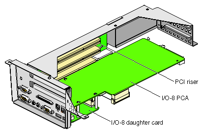
The I/O-8 board assembly consists of a main I/O-8 printed circuit assembly (PCA), an I/O-8 daughter card, and a PCI riser (refer to Figure A-8). The assembly provides I/O interface functions, the I/O connectors to the system back panel, and the L1 controller functions.
The I/O-8 PCA has the following connectors at the bulkhead:
One external SCSI connector
One 10BaseT/100BaseT auto-selecting Ethernet connector
One L1 console connector
Two USB 4-pin ports
One USB L1 port
Two serial ports
One real-time (RT) interrupt output
One RT interrupt input
The PCI riser provides a connection between the IP45 motherboard and the I/O-8 board assembly as well as two PCI card slots. The PCI riser has the following connectors:
One connector that connects the PCI riser to the IP45 motherboard
Two 64-bit universal PCI connectors that seat the PCI cards
One nonstandard PCI connector that connects the PCI riser to the I/O-8 board assembly
One 50-pin AMP connector that connects the PCI riser to the I/O-8 board assembly

Note: Refer to the SGI Supportfolio Online home page at http://support.sgi.com for a list of supported PCI option cards.
The SCSI backplane provides a connection between the internal SCSI interface on the I/O-8 board and up to two disk drives. The SCSI backplane supports Ultra3 SCSI LVD disks with a peak transfer rate of 160 MB/s. Refer to the SGI Supportfolio Online home page at http://support.sgi.com for an updated list of supported drives.
The chassis accommodates up to two sled-mounted 3.5-in. by 1.0-in. Ultra3 SCSI LVD drives. The backplane supports 10,000-RPM and 15,000-RPM drives.
The SGI Origin 300 base module uses a nonredundant modified WTX power supply with an input of 110/220 Vac (auto-sensing) and a maximum output of 460 W (3.3/5/12 Vdc). The DC power from the power supply is delivered via a cable harness, which has multiple connectors for power delivery.
The SGI Origin 300 with NUMAlink module system can use an AC-powered NUMAlink module or a DC-powered NUMAlink module. Logically, the AC-powered NUMAlink module and the DC-powered NUMAlink module are the same. Both NUMAlink modules route information between the Origin 300 base modules via the NUMAlink 3 interconnect. The NUMAlink modules consist of eight ports. Four ports can connect to four Origin 300 base modules. The other four ports, which carry USB signals, can connect to Origin 300 base modules or PCI expansion modules.
Physically, the AC-powered NUMAlink module differs from the DC-powered module in the following areas:
The AC-powered NUMAlink module contains an internal power supply, which receives AC voltage from a PDU or power strip. The DC-powered NUMAlink module receives DC voltage from a power bay.
The power connector at the rear of the AC-powered NUMAlink module is different from the power connector on the DC-powered NUMAlink module.
The rear of the AC-powered NUMAlink module does not have a power switch, a 12-Vdc LED, nor a 48-Vdc LED.
The NUMAlink modules require 2U of space within the rack and have the specifications that Table A-5 lists.
Table A-5. NUMAlink Module Specifications
Characteristic | Specification |
|---|---|
Height | 3.3 in. (83.82 mm) |
Width | 17.38 in. (441.45 mm) |
Depth | 27.5 in. (609.60 mm) |
Weight | 20 lb (9 kg) |
Input power (AC powered) | 110/220 Vac (~60 W) |
Input power (DC powered) | +48 Vdc (~60 W) |
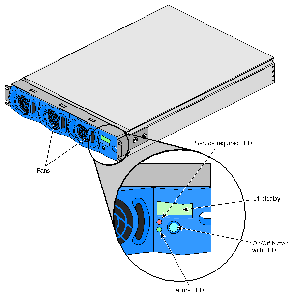
The AC- and DC-powered NUMAlink modules contain the following front-panel items (refer to Figure A-9):
L1 display is a 2-line by 12-character liquid crystal display (LCD) that displays status and error messages that the L1 controller generates.
On/Off button with LED enables you to manually power on and power off the module.
L1 controller LEDs function as follows:
On/Off button LED illuminates green when the internal components are powered on.
Service required LED illuminates orange to indicate that an item is not functioning properly (for example, a fan is off), but the NUMAlink module is still operating.
Failure LED illuminates red to indicate that a failure has occurred and the NUMAlink module is down.
Fans that provide N+1 redundant cooling for the module.

Note: The front of the NUMAlink module appears to display three cooling fans; however, only the middle and right fans are present.
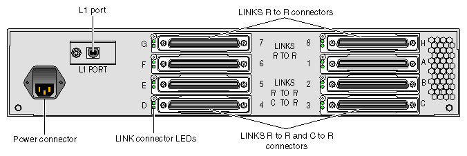
The AC- and DC-powered NUMAlink modules have the following rear-panel items (refer to Figure A-10 and Figure A-11):
PWR (power) connector:
Attaches the AC-powered NUMAlink module to the PDU or power strip via a power cable.
Attaches the DC-powered NUMAlink module to the power bay module via a DC power cable.
L1 port connector connects the internal USB hub of the NUMAlink module to the L2 controller. The internal USB hub receives the USB signals from the L2 controller via this port and distributes these USB signals to the L1 controllers of the attached Origin 300 base modules and PCI expansion modules.
LINKS R to R connectors (also referred to as ports 1, 6, 7, and 8, or A, F, G, and H) connect Origin 300 base modules to the NUMAlink module.
LINKS R to R and C to R connectors (also referred to as ports 2, 3, 4, and 5, or B, C, D, and E) connect Origin 300 base modules and/or PCI expansion modules to the NUMAlink module.
Besides NUMAlink signals, ports 2, 3, 4, and 5 transfer USB signals between the USB hub of the NUMAlink module and the L2 controller.
LINK connector LEDs. Each NUMAlink connector has two LEDs:
The green LED illuminates to indicate that a cable is connected properly between the NUMAlink module and another module.
The yellow LED illuminates to indicate that the L1 controller detected the “Remote Power OK” signal from the module on the other end of the cable.
The DC-powered NUMAlink module also contains the following rear-panel items:
Power switch powers on the L1 controller when moved to the 1 position; moving it to the 0 position powers off the L1 controller.
12-Vdc LED illuminates green when the power switch is in the On position and the power bay supplies 12 Vdc to the module.
48-Vdc LED illuminates green when the power bay supplies 48 Vdc to the module at the request of the L1 controller.
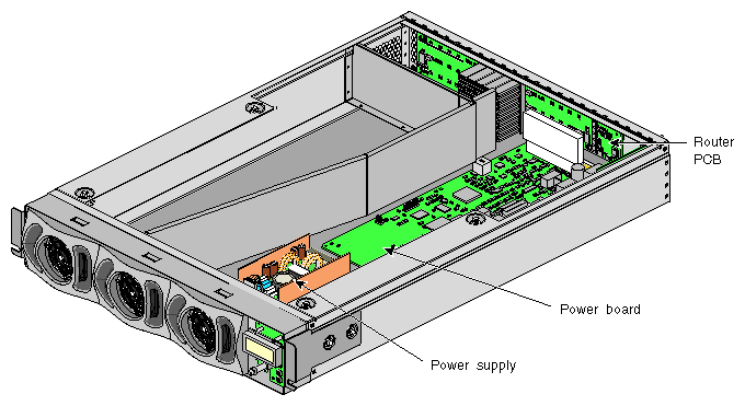
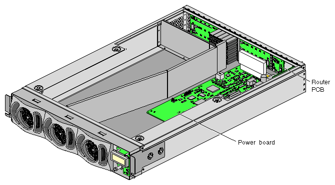
The AC- and DC-powered NUMAlink modules contain the following internal components, which are described in the subsections that follow (refer to Figure A-12 and Figure A-13).
Router printed circuit board (PCB)
Power board
L1 controller
The AC-powered NUMAlink module also contains a power supply (refer again to Figure A-12). The DC-powered NUMAlink module does not have an internal power supply.
A router PCB contains a router ASIC, a USB hub, and LINK connectors and LEDs. The router ASIC arbitrates for NUMAlink port access and has a crossbar unit that provides connection between the ports.
The USB hub is the interface between the L2 controller and the L1 controllers of the four modules that connect to ports 2, 3, 4, and 5. It receives the USB signals from the L2 controller via a USB port (labeled L1 Port). The USB hub is also the interface between the NUMAlink module L1 controller and the L2 controller.
The LINK connectors and LEDs are described in “Rear Components”.
The power board connects to the router PCB via the power connector. It contains a VRM and voltage regulators that convert the incoming 48 Vdc to voltage levels that the components within the module require. The power board also contains a serial ID EEPROM and the L1 controller logic.
The L1 controller monitors and controls the following environments: operating temperature, voltage margins, and system LEDs.
The L1 controller also reads component information from serial ID EEPROMs, provides a console connection, and interfaces with its own 2-line x 12-character LCD. The NUMAlink module L1 controller connects to the L2 controller via its internal USB hub and 4-pin USB port connector.
The L1 controller consists of the display, logic components, and a display cable. The display is located at the front of the module. The logic components are located on the power board. The cable connects the display to the logic components.
The four-port USB hub connects the L2 controller to the Origin 300 base modules that connect to ports 1, 6, 7, and 8 of the NUMAlink module.
Table A-6 lists the specifications of the USB hub.
Table A-6. USB Hub Specifications
Characteristic | Specification |
|---|---|
Height | 0.88 in. (22.23 mm) |
Width | 4.25 in. (107.95 mm) |
Depth | 2.75 in. (69.85 mm) |
Figure A-14 illustrates the USB hub. It consists of five ports (four ports connect to Origin 300 base modules and one port connects to the L2 controller) and a power adapter that connects the hub to a power distribution unit (PDU) or power strip.
The L2 controller is a rack-level controller; it communicates with all of the L1 controllers within the rack. For example, it receives status and error messages from the L1 controllers. The L2 controller is housed in a sheet metal box that is 1U high and is located at the top rear of the rack.
You can access the L2 controller via the system console.
Table A-7 lists the specifications of the L2 controller.
Table A-7. L2 Controller Specifications
Characteristic | Specification |
|---|---|
Height | 1.75 in. (44.45 mm) |
Width | 14.0 in. (355.6 mm) |
Depth | 6.0 in. (165.1 mm) |
Input power | +48 Vdc (~30 W) |
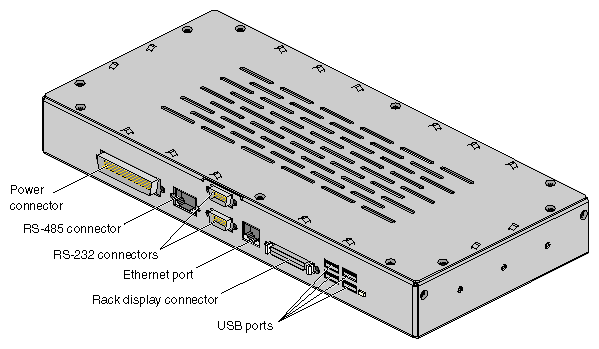
The L2 controller has the following connectors (refer to Figure A-15):
Power connector that connects the L2 controller to a power bay module or to a stand-alone power supply when the system has an AC-powered NUMAlink module.
Two RS-232 ports (DB-9) that connect the L2 controller to a modem.
10BaseT Ethernet port that connects the L2 controller to an Ethernet hub (system console that contains SGIconsole software).
Four USB ports ; two of these ports connect the L2 controller to the L1 port of the NUMAlink module and to the Origin 300 base modules that connect to NUMAlink module ports 1, 6, 7, and 8 via a USB hub.
The power bay can monitor, control, and supply AC power to as many as six power supplies; however, in this system, the power bay contains two or three power supplies. The third power supply is required when the system has four PCI expansion modules.
Each power supply inputs single-phase AC voltage and outputs 950 W at 48 Vdc and 42 W at 12 Vdc standby. The outputs of the power supplies are bused together. For example, when the power bay contains two power supplies, the power supplies are bused together to provide 1,840 W at 48 Vdc and 90 W at 12 Vdc standby of available power.
The power bay requires 3U of space within the rack and has the specifications that are listed in Table A-8.
Table A-8. Power Bay Module Specifications
Characteristic | Specification |
|---|---|
Height | 5.12 in. (130.00 mm) |
Width | 17.5 in. (443.0 mm) |
Depth | 22.008 in. to 23.898 in. |
Weight | 42.00 lb (19.05 kg) |
Table A-9 lists the specifications of the power supplies.
Table A-9. Power Supply Specifications
Characteristic | Specification |
|---|---|
Height | 4.86 in. (123.50 mm) |
Width | 2.74 in. (69.50 mm) |
Depth | 13.67 in. (347.30 mm) |
Weight | 7.50 lb (3.38 kg) |
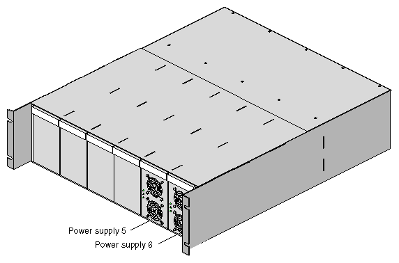
The front of the power bay seats the distributed power supplies (refer to Figure A-16). When the power bay contains two power supplies, the supplies reside in locations 5 and 6. The third power supply resides in location 4.
The power supplies are air-cooled devices; each power supply has two fans that move air from the front of the rack to the rear of the rack.
Each power supply has the following LEDs:
Table A-10 lists conditions of the power supplies and the corresponding states of the LEDs.
Table A-10. Power Supply LED States
| LED States |
|
|
|---|---|---|---|
Power Supply Condition | Power (Green) | PFAIL (Amber) | FAIL (Amber) |
AC voltage not applied to all power supplies | Off | Off | Off |
AC voltage not applied to this power supply | Off | Off | On |
AC voltage present; standby voltage on | Blinking | Off | Off |
Power supply DC outputs on | On | Off | Off |
Power supply failure | Off | Off | On |
Current limit reached on 48-Vdc output | On | Off | Blinking |
Predictive failure | On | Blinking | Off |
Each power supply also contains a serial ID EEPROM that identifies the model and serial number of the supply. The L1 controller of a connecting module reads this information via the DC power cable.
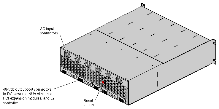
The power bay module has eight output connectors (refer to Figure A-17). A power cord connects one output connector to a DC-powered NUMAlink module, PCI expansion module, or L2 controller. This connection provides 12 Vdc standby, 48 Vdc, and monitoring signals.
| Note: The L1 controller of a connecting module can monitor the status and enable the output ports of the power bay. |
The power bay module also has six AC input connectors; one for each power supply location. For example, when the power bay contains two power supplies, connectors 5 and 6 connect to the power distribution unit (PDU). When the power bay contains three power supplies, connector 4 also connects to the PDU.
The power bay contains a motherboard that connects the power supplies to the connectors at the rear of the power bay; it serves as the power bus that buses the outputs of the power supplies together to produce 48 Vdc and 12 Vdc standby. The power bay motherboard also:
Contains overcurrent protection circuits for each power port.
Filters the DC voltage.
Contains a serial ID EEPROM that indicates the model and serial number of the power bay.
Seats the system management card.
The system management card is the control system for the power bay. It contains the logic that powers the power supplies and ports on and off and a serial ID EEPROM that indicates the model and serial number of the unit. The L1 controller uses the RS-485 signals of the DC power cables to read this PROM.
The system management card also performs the following functions:
Interfaces with the L1 controllers.
Provides a communication link between the power supplies and the power bay.
Monitors faults.
Provides access to data for the power bay and power supplies.
The PCI expansion module is an optional device that provides an additional twelve PCI slots for the Origin 300 system. As many as four PCI expansion modules can reside in this system; the number of PCI expansion modules depends on the number of base modules in the system (refer to Table A-11).
Table A-11. Number of Supported PCI Expansion Modules
Number of Base Modules | Supported PCI Expansion Modules |
|---|---|
Two | Two |
Three | Three |
Four | Four |
Five | Three |
Six | Two |
Seven | One |
Eight | Zero |
The PCI expansion module contains 6 buses; each bus can seat one or two 3.3-V or universal PCI cards that mount on PCI carriers. Each bus supports either two 33-MHz PCI cards or two 66-MHz PCI cards.
The PCI expansion module communicates with the Origin 300 base modules and the L2 controller via the NUMAlink module. The PCI expansion modules connect to the NUMAlink module via ports 2, 3, 4, and 5.
| Note: For more information about the PCI expansion module, refer to the PCI Expansion Module User's Guide (007-4499-00x). |
Table A-12 lists the specifications of the PCI expansion module.
Table A-12. PCI Expansion Specifications
Characteristic | Specification |
|---|---|
Height | 7.0 in. (177.8 mm) |
Width | 17.5 in. (444.5 mm) |
Depth | 27.5 in. (698.5 mm) |
Weight | 70.0 lb (31.5 kg) |
Input power | +48 Vdc (~250 W) |
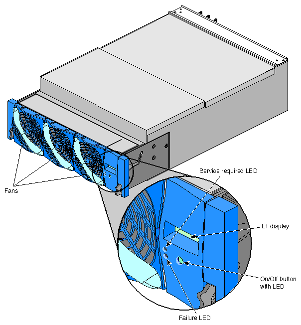
The PCI expansion module contains the following front-panel items (refer to Figure A-18):
L1 display is a 2-line by 12-character liquid crystal display (LCD) that displays status and error messages that the L1 controller generates.
On/Off button with LED enables you to manually power on and power off the module.
L1 controller LEDs function as follows:
On/Off button LED illuminates green when the internal components are powered on.
Service required LED illuminates orange to indicate that an item is not functioning properly (for example, a fan is off), but the PCI expansion module is still operating.
Failure LED illuminates red to indicate that a failure has occurred and the PCI expansion module is down.
Three fans that provide N+1 redundant cooling for the module.
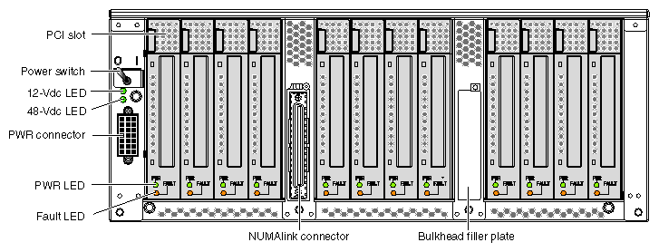
The PCI expansion module has the following rear-panel items (refer to Figure A-19):
Power switch powers on the L1 controller when moved to the 1 position; moving it to the 0 position powers off the L1 controller.
12-Vdc LED illuminates green when the power switch is in the On position and the power bay supplies 12 Vdc to the module.
48-Vdc LED illuminates green when the power bay supplies 48 Vdc to the module at the request of the L1 controller.
PWR (power) connector attaches to the power bay via a DC power cable.
PCI slots seat the PCI cards. Each slot has two LEDs:
PWR (power) LED illuminates green when the PCI card carrier is installed securely and is receiving power.
Fault LED illuminates orange when a fault occurs with the PCI card.
NUMAlink connector attaches the PCI expansion module to the NUMAlink module via a NUMAlink cable.
Bulkhead filler plate covers the unused connector slot so that air flows properly through the module.
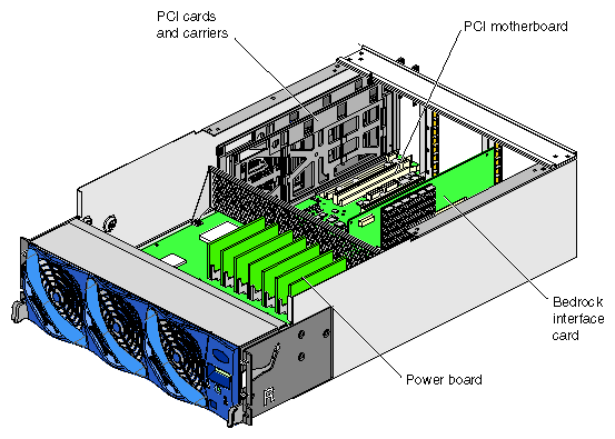
The PCI expansion module contains the following components, which are shown in Figure A-20 and discussed in the subsections that follow:
Bedrock interface card
PCI motherboard
Power board
L1 controller
The PCI expansion module houses one Bedrock interface card (BIC) that contains a Bedrock ASIC, a NUMAlink 3 connector, a power connector, and a connector that connects to the PCI motherboard.
The Bedrock ASIC enables this card to transfer signals between an Origin 300 base module and the PCI expansion module via the NUMAlink module; the Bedrock ASIC passes these signals to the Xbridge ASICs that are located on the PCI motherboard. The Bedrock ASIC receives power from the PCI motherboard via the power connector.
The NUMAlink 3 connector of the BIC is the left connector when you face the rear of the PCI expansion module. The right connector contains a bulkhead filler plate to maintain proper airflow through the module.
The PCI motherboard contains 12 PCI slots and three Xbridge ASICs. The Xbridge ASICs are the interface between the Bedrock ASIC on the BIC and the PCI cards. The PCI motherboard also contains a serial ID EEPROM that contains component information.
The power board contains the logic components of the L1 controller, voltage regulator modules (VRMs), and a DC-to-DC converter. The VRMs and the DC-to-DC converter convert the incoming 48 Vdc to voltage levels required by the components within the module.
The L1 controller monitors and controls the environment of the PCI expansion module. It consists of a display, logic components, and an internal cable. The display is located on the front of the module. The L1 controller logic components are on the power board. The internal cable connects the display to the logic components.
The SGI TP900 storage module is a rackmountable, 2U-high, 8-drive storage system that provides JBOD (just a bunch of disks) storage for the Origin 300 base module. The drive backplane connects the 8 drives on one SCSI bus. As an option, the storage system can also be configured on two SCSI buses (2 strings of 4 drives).
| Note: For more information about the TP900 storage module, refer to SGI Total Performance 900 Storage System User's Guide. |
Table A-13 lists the specifications of the TP900 storage module.
Table A-13. TP900 Storage Module Specifications
Characteristic | Specification |
|---|---|
Height | 3.37 in. (85.70 mm) |
Width | 17.6 in. (447.0 mm) |
Depth | 21.46 in. (545.00 mm) |
Input power | 100 - 254 Vac (~175 W) |
Weight: Maximum configuration Empty enclosure |
48.5 lb (22.0 kg) 14.3 lb (6.5 kg) |
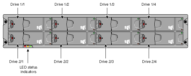
The front of the SGI TP900 chassis consists of eight drive bays that contain either disk drive carrier modules or dummy carrier modules, which are discussed in the subsections that follow. The front of the TP900 is four bays wide by two bays high. The bays are numbered 1 and 2 from top to bottom and 1 to 4 from left to right. Refer to Figure A-21.
The front of the chassis also contains the three status LEDs that are listed in Table A-14.
LED | Status |
|---|---|
System status | Green signifies that power is applied to the enclosure. |
Power status | Green signifies that the power supplies are functioning normally. |
Cooling status | Green signifies that all fans are functioning normally. |
The disk drive carrier module is a die-cast aluminum carrier that houses a single 1.0-in. high, 3.5-in. disk drive.
Each drive carrier has two LEDs: a green LED and an amber LED. In normal operation, the green illuminates and flickers as the drive operates. The amber LED illuminates when a fault occurs.
This carrier has a handle that enables you to insert and remove the carrier from the drive bay. The handle also has an anti-tamper lock that locks the handle in place; therefore, the carrier cannot be removed from the drive bay. When the handle is locked, a red indicator is visible in the handle. When carrier is unlocked, a white indicator is visible.
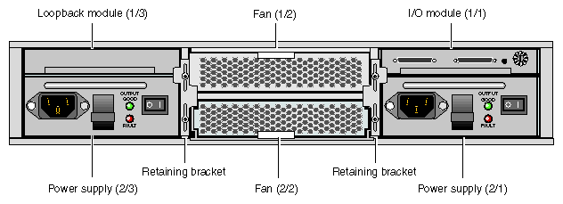
The rear of the TP900 storage module contains six bays that house power supply, cooling, and SCSI I/O modules. Refer to Figure A-22. The rear of the TP900 storage module is three bays wide by two bays high. The bays are numbered 1 and 2 from top to bottom and 1 to 3 from right to left.
The TP900 rear bays house the following components, which are discussed in the subsections that follow.
Power supply module
Input/output (I/O) module
Cooling module
Blank modules
The SGI TP900 storage system requires one 350-W power supply module, which is mounted in the rear of the system. Power supply voltage operating ranges are nominally 115 V or 230 V and are selected automatically.
Optionally, a second power supply module can be added to the TP900 system to provide redundant power. In this redundant configuration, the power supply modules operate together; if one power supply module fails, the other module supplies power until the faulty unit is replaced.
The power supply module contains two LEDs that are located on the front panel of the power supply. The green LED indicates power output. The amber LED indicates a power supply failure.
The I/O module contains two VHDCI connectors and a switch to set the SCSI ID range. The SGI TP900 storage module supports one I/O module for a 1 x 8 configuration and two I/O modules for a 2 x 4 configuration. The 1 x 8 configuration creates a SCSI bus structure with 1 string of 8 drives. The 2 x 4 configuration creates a SCSI bus structure with 2 strings of 4 drives.
| Note: When only one I/O module is present in the system, the other I/O module location contains a loopback module that has no external connectors. |
The cooling module consists of fans that pull warm air from a plenum behind the drive backplane and exhaust the warm air at the rear of the enclosure. The cooling modules connect to the backplane for power and status signal connections.
The TP900 system requires one cooling module, which is mounted in the rear of the system. Optionally, a second cooling module can be added to the system to provide redundant cooling. In this redundant configuration, the cooling modules operate together; if one module fails, the other module adequately cools the system until the faulty unit is replaced.
The cooling module has two LEDs that are located on the front panel of the cooling module. The green LED indicates that the cooling module is functioning properly. The amber LED indicates a fan failure.
The Myrinet-2000 switch is a 16-port switch that provides the network fabric necessary to cluster up to four 32-processor Origin 300 with NUMAlink module systems. It is a high-performance packet communication and switching technology that interconnects the clusters of base modules via full-duplex 2+2 Gb/s links.
The Origin 300 base modules connect to the switch via a fiber cable and a Myrinet PCI card.
Table A-15 lists the specifications of the Myrinet-2000 switch.
Table A-15. Myrinet-2000 Switch Specifications
Characteristic | Specification |
|---|---|
Height | 3.40 in. (36.36 mm) |
Width | 17.0 in. (431.8 mm) |
Depth | 18.0 in. (457.2 mm) |
Input power | 220 Vac (~40 W) |
Weight | 15.0 lbs (6.8 kg) |
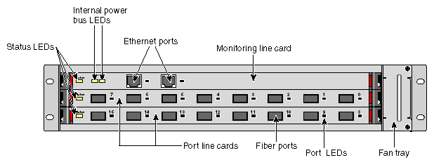
The front of the Myrinet-2000 switch contains the following components:
The monitoring line card monitors and controls the Myrinet-2000 switch. It has two microcontrollers: one microcontroller monitors internal functions, voltages, and temperatures of the monitoring line card, and the second microcontroller communicates with the other internal components of the switch via serial communication links.
The monitoring line card communicates externally via one of the Ethernet ports and uses a standard firmware that runs under VxWorks, a real-time operating system. You can download updated firmware and receive status information via the Ethernet port.
The panel of the monitoring line card includes the following items:
Two Ethernet ports
Two Ethernet port LEDs (one LED for each Ethernet port) that illuminate green when the ports are connected to active ports; they blink when there is traffic on the ports
One status LED that illuminates green when the monitoring line card is operating properly; it illuminates yellow when there is a fault
Two +12 V power bus LEDs that illuminate green when the power is on
One label that displays the Ethernet MAC address

Note: The Ethernet ports are redundant; therefore, they have the same MAC address.
The Myrinet-2000 switch contains 2 port line cards:
One spine port line card that contains 8 fiber ports
One switch port line card that contains 8 fiber ports and one 16-port crossbar
The fiber ports (via fiber cables) connect to Myrinet PCI cards that are installed in the Origin 300 base modules. The 16-port crossbar provides links between the hosts that connect to the fiber ports.
In Figure A-23, the switch port line card is located below the spine card.
The port line cards have the following LEDs:
Status LED - The status LED illuminates green to indicate that the card has passed its self-test and all voltages, temperatures, and internal status bits are at nominal levels; it illuminates yellow to indicate a fault. The status LED is controlled by the microcontroller of that line card. The monitoring line card can provide more detailed information about the status of the port line card, including the type of port line card, its serial number, and internal voltages and temperature.
Port LEDs - Each fiber port has an LED that illuminates green when the port is cabled to an active port; it blinks when traffic is flowing.
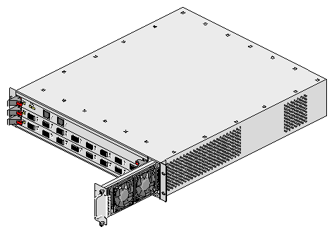
The fan tray contains fans that cool the components within the switch (refer to Figure A-24).
The rear of the Myrinet-2000 switch contains an input power plug (refer to Figure A-25). This plug connects to a PDU or power strip within the rack and supplies 220 Vac to an internal power supply.
Internally, the Myrinet-2000 switch contains a power supply and a backplane. The power supply produces +12 V that is distributed to the components that make up the Myrinet-2000 switch via a backplane. Local voltage regulators use the +12 V to produce +3.3 V, +2.5 V, and/or +1.25 V, which are the voltages required by the internal circuitry.
The backplane connects the internal components of the Myrinet-2000 switch. For example, the backplane supplies the following connections:
Connections between the monitoring line card and the port line cards (serial links)
Connections between the port line cards
Connections among the power supply (+12 V) and the monitoring line card, the port line cards, and the fan tray
