This chapter contains technical information about the Silicon Graphics Fuel visual workstation. The following topics are covered:
Table A-1 shows the physical environment specifications for the Silicon Graphics Fuel visual workstation.
Table A-1. Physical Environment Specifications
Feature | Specification |
|---|---|
Workstation dimensions | Height: 19.0 in. Width: 8.9 in. at the bezel 8.3 in. on the rest of the chassis Depth: 19.4 in. from front of bezel to rear of chassis |
Workstation weight Base system |
42 lb. (19 kg) |
Power requirements | Voltage and frequency: 100-240 VAC, 50-60 Hz, 7.0-3.0 A, 430 W |
Voltage and frequency | 50-60Hz and 100-120/200-240 VAC |
Temperature Tolerance | +5 o C (13.6 oF) to +35 oC (95 oF) 5000 ft. ASL or less +5 o C (13.6 oF) to +30o C (81.6 oF) 5000 ft. ASL to 10,000 ft. ASL |
Temperature tolerance | -40 C (-40 oF) to +60 o C (140o F) |
Relative humidity | 10% to 80% operating (no condensation) 10% to 95% non-operating (no condensation) |
Heat dissipation | 1075 Btu/hr |
Maximum altitude | 10,000 ft. (3,049 m) operating 40,000 ft. (12,195 m) non-operating |
Vibration, sine sweep (operating) | 0.01”, 5-19 Hz; 0.25 G, 19-500 Hz |
Vibration, sine sweep (non-operating) | 0.10”, 3-10 Hz; 0.5 G, 10-200 Hz |
Vibration, random | 0.10 Grms for 15 minutes |
Vibration, random | 1.15 Grms for 15 minutes |
Shock, half-sine wave (operating) | 30 G, 3 msec (vertical); 15 G, 3 msec. (horizontal) |
Shock, trapezoidal wave (non-operating) | 30 G, 200 in./sec. |
Sound power | 4.29 bels |
Sound pressure | 38.8dBA at operator position per ISO 7779 |
Table A-2 shows the power supply specifications for the Silicon Graphics Fuel visual workstation.
Table A-2. Power Supply Specifications
Feature | Specification |
|---|---|
AC line voltage rating | 90-264 VAC RMS nominal, 47-63 Hz |
Output ratings | 45 amps @ 3.3 V |
| 27 amps @ 5 V |
| 16 amps @ +12 V 18 amps @ +12 V (digital) 0.6 amps @ -12 V |
| 3 amps @ +5 stand by |
Combined output Limit | Combined 3.3-V, 5-V, and 12-V output is limited to 300 watts. |
This section contains specifications and port pinout information for the I/O ports of the Silicon Graphics Fuel visual workstation. The ports are discussed in the following sections:
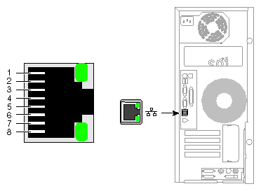
The workstation auto-selects the Ethernet port speed and type (duplex vs. half-duplex) when the workstation is booted, based on what it is connected to. Figure A-1 shows the Ethernet port.
Table A-3 shows the cable pinout assignments for the Ethernet port.
Table A-3. Ethernet 10-Base-T/100-Base-T Port Pinout
Pin | Assignment |
|---|---|
1 | Transmit+ |
2 | Transmit– |
3 | Receive+ |
4 | (Reserved) |
5 | (Reserved) |
6 | Receive– |
7 | (Reserved) |
8 | (Reserved) |
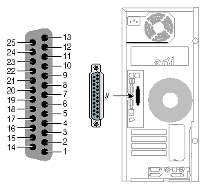
The parallel port on the workstation is bi-directional and supports both EPP and ECP modes. Figure A-2 shows the IEEE 1284-A parallel port.
Table A-4 shows the cable pinout assignments for the IEEE 1284-A parallel port.
Table A-4. IEEE 1284-A Parallel Port Pinout
Pin | Assignment | Pin | Assignment |
|---|---|---|---|
1 | Strobe | 14 | AutoFd |
2 | Data 1 (least significant bit) | 15 | Fault |
3 | Data 2 | 16 | Init |
4 | Data 3 | 17 | SelectIn |
5 | Data 4 | 18 | Signal Ground |
6 | Data 5 | 19 | Signal Ground |
7 | Data 6 | 20 | Signal Ground |
8 | Data 7 | 21 | Signal Ground |
9 | Data 8 (most significant bit) | 22 | Signal Ground |
10 | Ack | 23 | Signal Ground |
11 | Busy | 24 | Signal Ground |
12 | Error | 25 | Signal Ground |
13 | Select |
|
|
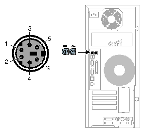
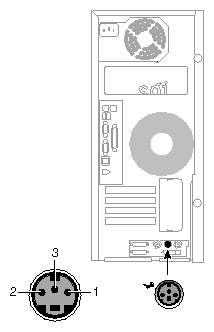
The workstation uses keyboards and mouse devices that are PS/2-compatible. The combined current draw of the keyboard and mouse is limited to 0.5 amps at +5V. Figure A-3 shows the keyboard and mouse ports.
Table A-5 shows the pinout assignments for the keyboard and mouse ports.
Table A-5. Keyboard and Mouse Port Pinout
Pin | Assignment |
|---|---|
1 | Keyboard/mouse data |
2 | (Reserved) |
3 | Ground |
4 | Keyboard/mouse power (+5V) |
5 | Keyboard/mouse clock |
6 | (Reserved) |
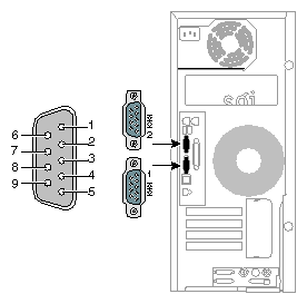
The workstation features two 9-pin serial ports. These ports are capable of transferring data at rates as high as 230 kbps. Other features of the ports include:
Programmable data, parity, and stop bits
Programmable baud rate and modem control
Figure A-4 shows a serial port.
Table A-6 shows pinout assignments for the 9-pin male DB-9 connector.
Pin | Assignment | Description |
|---|---|---|
1 | DCD | Data carrier detect |
2 | RXD | Receive data |
3 | TXD | Transmit data |
4 | DTR | Data terminal ready |
5 | GND | Signal ground |
6 | DSR | Data set ready |
7 | RTS | Request to send |
8 | CTS | Clear to send |
9 | RI | Ring indicator |
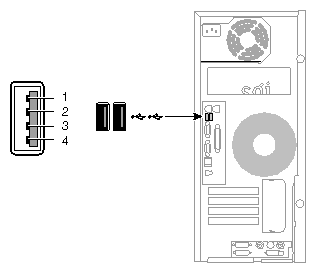
The workstation is equipped with two USB-A ports. These ports support both low-speed (1.5 Mbps) and high-speed (12 Mbps) USB devices. They are connected to a USS-312 USB controller, which uses a 32-bit, 33-MHz PCI interface. Figure A-5 shows the USB-A ports.
Table A-7 shows the pinout information for the USB-A ports.
| Note: The Silicon Graphics Fuel visual workstation also has a USB-B port, but this port is used only for system maintenance. Do not attempt to connect any devices to the USB-B port. |
This section contains cable pinout information for serial cables that you can connect to your Silicon Graphics Fuel visual workstation. It also describes SGI serial port converters. The following topics are covered:
For serial printers and dumb terminals, use a 3-wire standard PC cable. Table A-8 shows the cable connector pinout assignments for this cable.
| Note: For a 3-wire cable and no hardware flow control modem, you must use the /dev/ttyd* command devices in the configuration files. For more detailed information, see the serial man page. To access the man page, select Help > InfoSearch > Man pages from the Toolchest or place the cursor in the console window and type man serial. |
Table A-8. Printer/Dumb Terminal Cable Pinout
Signal Description | Pin Number | Pin Number |
|---|---|---|
| 1 | NOT CONNECTED |
RXD | 2 | 2 |
TXD | 3 | 3 |
| 4 | NOT CONNECTED |
GND | 5 | 7 |
| 6 | NOT CONNECTED |
| 7 | NOT CONNECTED |
| 8 | NOT CONNECTED |
| 9 | NOT CONNECTED |
Use a full-handshake (includes RTS and CTS) PC modem serial cable for a modem with RTS/CTS flow control. Table A-9 shows the cable connector pin assignments for this cable.
You can use this cable for all serial devices except those that do not need RTS flow control. If you add a null modem adapter to one end of the cable, you can still use it with devices like serial printers and dumb terminals that do not need RTS flow control. You can purchase the full-handshake PC modem serial cable from SGI or your local service provider.
| Note: If you are attaching a modem with modem signals and RTS/CTS flow control, you must use the /dev/ttyf* command devices in the configuration files. For more detailed information, see the serial man page. To access this man page, select Help > InfoSearch > Man pages from the Toolchest or place the cursor in the console window and type man serial. |
Table A-9. PC Modem Cable Pinout
Signal Description | Pin Number | Pin Number |
|---|---|---|
DCD | 1 | 8 |
RXD | 2 | 3 |
TXD | 3 | 2 |
DTR | 4 | 20 |
GND | 5 | 7 |
DSR | 6 | 6 |
RTS | 7 | 4 |
CTS | 8 | 5 |
RI | 9 | 22 |
The workstation's serial ports conform to the PC standard pinout for EIA standard RS-232 signals.
The purpose of the adapter cable is to allow the workstation to use standard PC serial devices. Table A-10 shows the adapter cable pinout for a standard PC or Macintosh serial port.
Table A-10. Female DB-9 to Female MiniDIN8 Adapter Cable Pinout
From: Female DB | To: MiniDIN8 | PC Signal | Macintosh Signal |
|---|---|---|---|
1 | 7 | DCD | GPi |
2 | 5 | RD | RxD- |
3 | 3 | TD | TxD- |
4 | 1 | DTR | TxD+ |
5 | 4 | SG | SG |
6 | 8 | DSR | RxD+ |
7 | 6 | RTS | HSKo |
8 | 2 | CTS | HSKi |
9 | Unused | RI | Unused |
The purpose of the following adapter cable is to support ANSI/SMPTE Standard 107M-1992.
Table A-11 shows the pinout for a female DB-9 to female DB-9 adapter cable.
Table A-11. Female DB-9 to Female DB-9 Adapter Cable Pinout
Female DB-9 Connected | Female DB-9 Connected |
|---|---|
1 | Unused |
2 | To DB9 -2 (RxD-) |
3 | To DB9-8 (TxD-) |
4 | Unused |
5 | To DB9-6 and DB9-4 (GND) |
6 | To DB9-7 (RxD+) |
7 | To DB9-3 (TxD+) |
8 | Unused |
9 | Unused |
| Note: For more detailed information, see the serial man page. To access it, open an IRIX shell and enter man serial |
You can also access man pages by selecting Help > InfoSearch and entering man serial.
This section provides specifications for the following ports:
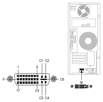
Figure A-6 shows the DVI-I video port.
Table A-12 shows the port pinout assignments for DVI-I port(s).
Table A-12. DVI-I Video Port Pinout
Pin | Assignment | Pin | Assignment |
|---|---|---|---|
1 | DATA 2- | 16 | HOT_POWER |
2 | DATA2+ | 17 | DATA 0- |
3 | SHIELD 2/4 | 18 | DATA 0+ |
4 | DATA 4- | 19 | SHIELD 0/5 |
5 | DATA 4+ | 20 | DATA 5- |
6 | DDC_CLOCK | 21 | DATA 5+ |
7 | DDC_DATA | 22 | SHIELD CLOCK |
8 | VSYNC | 23 | CLOCK - |
9 | DATA 1- | 24 | CLOCK + |
10 | DATA1+ | C1 | A_RED |
11 | SHIELD 1/3 | C2 | A_GREEN |
12 | DATA 3- | C3 | A_BLUE |
13 | DATA 3+ | C4 | HYNSC |
14 | DDC_POWER | C5 | A_GROUND2 |
15 | A_GROUND1 | C6 | A_GROUND3 |
Table A-13 lists the scan rates supported by the VPro graphics board.
Table A-13. Supported VPro Graphics Board Scan Rates
Format | Supported by V10 8bpp | Supported by V10 16bpp | Supported by V12 |
|---|---|---|---|
1024x768 at 60Hz,75Hz, and 96Hz-Stereo | yes | yes | yes |
1280x1024 at 59, 60, 72, 75, 85Hz, and 96Hz-Stereo | yes | yes | yes |
1280x1024 at 100Hz Stereo | yes |
| yes |
1280x720 at 60 and 72 Hz | yes | yes | yes |
1280x1024 at 30 Hz interlaced | yes |
| yes |
1280x960 at 30 Hz interlaced | yes |
| yes |
1600x1024 at 83 Hz | yes |
| yes |
1600x1200 at 60, 72, and 75 Hz | yes | no | yes |
1920x1035 at 30 Hz interlaced | yes |
| yes |
1920x1080 at 30 Hz interlaced | yes |
| yes |
1920x1200 at 60 Hz | yes |
| yes |
1920x1200 at 25 and 30 Hz | yes |
| yes |
The following diagram shows the Stereo View port.
Table A-14 shows the cable pinout assignments for the Stereo View port on the VPro graphics board.
Table A-14. Stereo View Pinout Assignments
Pin | Assignment |
|---|---|
1 | +12 V DC output to Stereo View device |
2 | Ground |
3 | Stereo left/right Eye signal (1=left, 0=right) (STEREO_LEFT) |
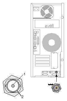
The following diagram shows the Genlock port.
Table A-15 shows the cable pinout assignments for the Genlock port on the VPro graphics board
Table A-15. Genlock Pinout Assignments
Pin | Assignment |
|---|---|
1 | Genlock Input/output video or 3.3V TTL signal levels |
2 | Sigma - return ground |
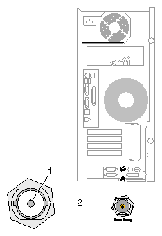
The following diagram shows the Swap Ready port.
| Note: The swap ready port is not functional with this release, but may be at a future date. |
Table A-16 shows the cable pinout assignments for the Swap Ready port on the VPro graphics board.
Table A-16. Swap Ready Pinout Assignments
Pin | Assignment |
|---|---|
1 | Swapbuffer gang sync open Collector I/O |
2 | Signal return ground |
