Everyone has a unique way of describing the different parts of the format. To standardize the nomenclature of the different formats, the video format compiler declares names and properties for the different portions of video timing. In this chapter, you will find information on the following topics:
The compiler's definition of The Horizontal Line
The compiler's definition of The Vertical Interval
The differences in the Level of Sync
How The Field of the Format is assembled and how it differs from the frame
Definitions of Components of the frame
The Silicon Graphics definition and use of The Pixel-to-Clock Ratio
This chapter is very much a tutorial. If you are familiar with the nomenclature Silicon Graphics uses in video formats, you can skip this chapter, using it only as reference.
What else is in a frame of video besides the pixels on the screen? Plenty!
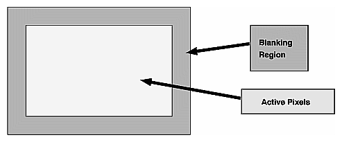
Figure 3-1 shows the geometric relationship between the active pixels—the part of the frame containing the picture you see on the screen—and the blanking region of a video frame. Blanking commonly consumes as much as 25% of a video frame, quite a lot for something you never see! So why include it?
We need the blanking region because of our terrible master: the cathode-ray tube (CRT). (Throw in a dash of convention, a bit of backward compatibility, and a slice of history, and you are up to 25%.) Old cathode-ray tubes, as well as many contemporary versions, need time and signaling information to manipulate the direction of the spray of electrons on the phosphorescent surface of the screen. Let us explain with a picture of the screen.
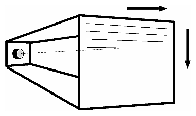
The screens of a most cathode ray tubes are drawn in a series of lines, left to right and top to bottom. When the monitor finishes drawing one line and reaches its right-most excursion, the beam is turned off (it is blanked) while the monitor returns the beam to the left side of the screen. A similar thing happens when the last line on the screen is finished drawing: the beam traverses to the top of the frame, ready to repeat its Sisyphusian task.
In the video format, what triggers the beam to return to the left side and to the top? It is the magic of synchronization signals. Synchronization signals are special pulses in the blanking region that tell the monitor the position at the beginning of the line; they also provide the frame with some geometric stability by lining up the left side of every line.
Each line of the video frame consists of well-defined regions. The most interesting region is that containing the active pixels (the picture drawn on the screen), but the blanking region is needed to define the beginning and ending of each line.
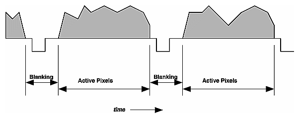
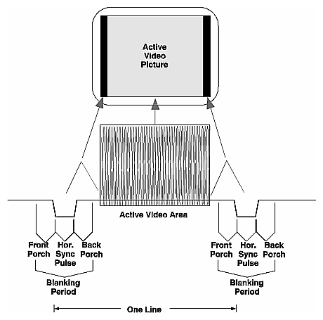
Figure 3-3 shows a typical line of a frame that contains active pixels. This figure shows active lines preceding and following the full line in the middle. The gray area—the picture content of the active pixel area—is variable because the picture in each line is different from the other.
You can see the blanking regions that separate the active pixels in each horizontal line. These are known as horizontal blanking regions because they constitute the black (or blanked) area between two horizontal lines. Typically, all lines in the frame containing active pixels have identical active and blanking geometries.
The synchronization pulse (the sync pulse) is the downward pulse in the blanking region. This pulse triggers the monitor to stop moving the beam in the rightward direction and resume drawing on the left side, one line lower. The horizontal line begins at the falling edge of one sync pulse and ends at the falling edge of the next sync pulse.
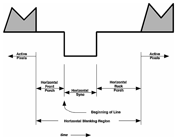
In Figure 3-4, you can see detail of the horizontal blanking region with the active pixels of the previous line terminating on the left side of blanking and those of the next line beginning on the right side of blanking. The components of the horizontal line are as follows:
The active pixels contain the picture content — the visible pixels.
The horizontal front porch is the period of the line between the active pixels and the beginning of the horizontal sync pulse.
The horizontal sync pulse is a change in voltage of the video signal. It is this change in voltage that triggers the monitor to stop its rightward progress and begin drawing again on the left side of the screen. The line begins with the start of the horizontal sync pulse (and ends with the start of the next horizontal sync pulse).
The horizontal back porch is the period of time between the end of the horizontal sync pulse and the active pixels.
The front and back porches provide some dead time where the monitor can be black before and after the active portion of the picture; this blackness is particularly important during the period of time the electron beam flies back the screen's left side to start drawing once again. In composite video formats such as NTSC, PAL, and SECAM, the horizontal back porch also contains the color burst, a color calibration reference.
If you are writing a video format because you have a special monitor, you need to know the durations of each of the different sections of the line. The durations themselves are usually given in time units, although sometimes the durations are supplied in pixels (in which case you should use the duration of a pixel).
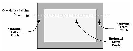
If you compare a horizontal line in Figure 3-5 to Figure 3-4, you can see a correspondence in the lines that contain active pixels. The horizontal front porch is the blanking region to the right of the active pixels in Figure 3-5; the horizontal back porch is to the left of the active pixels. The horizontal sync pulse cannot be shown in this kind of picture: it triggers the beam to fly back to the left side to screen to begin painting again.
All this talk of horizontal brings up a term used in video shorthand notation: the horizontal line is often referred to by the single roman letter H. The term is used so often that it now defines even the length of a horizontal line: One H.
The diagram in Figure 3-6 wraps up our discussion of the horizontal interval, showing a single line of active video (shown in grey) and surrounded by two horizontal blanking regions (or periods).
The vertical blanking region is similar in function to the horizontal blanking region: it has dead time that allows the monitor to display black picture content and a synchronization signal that directs the electron beam to fly back to its starting position. However, one begins to think vertically instead of horizontally.
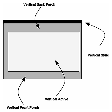
Figure 3-7 shows the vertical regions that are analogous to the horizontal regions found in Figure 3-5. You can see that each of the regions is longer than that of its horizontal counterpart, measured in lengths of multiple lines instead of portions of a line. The vertical sync cannot be shown well in a screen orientation illustration such as Figure 3-7 because sync triggers the beam to fly back to the top of the screen so the monitor can begin to show the next active area; it is represented here by a black band at the top of the frame.
Normally, one thinks of a video frame consisting of each of these regions. However, video formats consisting of more than one field have one vertical blanking region for each field; in this circumstance, the vertical front porch of one field is followed by the vertical sync of the next field.
To formalize the definition, the components of the vertical blanking region are as follows:
The active lines, those containing the rendered frame buffer contents.
The vertical front porch, the lines between the vertical sync and those containing active.
The vertical sync, the lines containing one or more vertical sync pulses. The frame begins at the start of vertical sync. In video formats with more than one field, each field begins with a vertical sync.
The vertical back porch, the lines between those containing active and those containing vertical sync pulse(s).
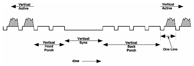
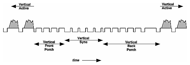
In Figure 3-8, you can see a vertical blanking region for a typical video format. The scale is much larger than that shown in the diagrams of “The Horizontal Line,” with each of the different components measuring more than one line (the number of lines varies, depending on the format). The figure shows some of the lines of the previous field followed by the vertical front porch, the vertical sync, the vertical back porch, and the lines of the next field.
The vertical sync pulse triggers the monitor to stop its downward trek at the end of each line. When it receives the vertical sync pulse, the monitor starts drawing new lines at the top of the screen.
Each line in the frame is numbered, with the first line beginning with the beginning of the vertical sync pulse. A specific point in the frame is usually referenced by line number and an offset (in time units) into the line.
The vertical interval shown in Figure 3-8 is characteristic of a video format type known as block sync; you can see the vertical sync is a single long synchronization pulse. The block sync is common enough that a typical geometry of this form of pulse is included in the block sync template; see Chapter 2, “Using the Block Sync Template” for information on how the block sync template works.
Although block sync type of video format is very common, other types of sync are also in general use. Another popular type of video format is that called commercial sync, which contains smaller pulses in place of the large sync pulse.
The smaller pulses of vertical sync shown in Figure 3-9 act in the same way as the long sync pulse does in the block sync type of video format: vertical sync triggers the monitor to start drawing at the top of the screen. This commercial sync format also has short pulses through vertical front porch and some of vertical back porch. Characteristic of the commercial sync type of video format, these pulses are called equalization pulses and ease the monitor into and out of vertical sync. The half-line pulses in vertical sync are known as serration pulses.
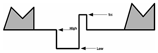
Most video formats have only two levels of sync, low and high. Also, some monitors (notably, those for high-definition television, or HDTV) require an additional third level of sync called tri-level.
You can see the three different levels of sync in Figure 3-10:
Low, also known as synchronization level. This is the lowest possible excursion of a sync signal.
High, also known as blanking level. This is the level attained during blanking when sync signals do not drive the level otherwise.
Tri, used for tri-level sync. This level of sync is at a pre-defined level, higher than the blanking level.
Thus far, we have discussed formats with only one field; that is, one contiguous set of video lines surrounded by the front and back porches. Formats with only one field are sometimes described as progressive scan formats. This single progression across and down the screen differs from the pattern used by multiple-field formats that may need to make many passes to draw the entire frame.
In the following sections, you can read about the following topics:
“Interlaced Formats,” where lines are interleaved
“Stereo Formats,” where the screen layout remains constant but content differs
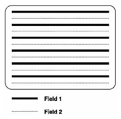
The layout of the lines in Figure 3-11 shows the interleaving of lines of a typical two-field interlaced video format. In the first field of this example, all the odd-numbered lines are drawn. When the first field concludes, the drawing starts again at the top of the screen but only the even-numbered lines are drawn. This differs from the line layout of the progressive-scan frame shown in Figure 3-2 in which every line is drawn from top to bottom.
The interlacing layout may differ from one video format to the next. Although the example in Figure 3-11 showed the first field containing the odd-numbered lines, a different video timing format may have the even-numbered lines in the first field.
The format shown in Figure 3-11 is has two fields, typical for interlaced formats. However, there is no prohibition against formats with many more fields, if the monitor requires it. Some output generation hardware may impose additional restrictions on the number of fields you can create.
Silicon Graphics offers two different types of stereo:
Per-Window Stereo, sometimes called new-style stereo. This stereo format allows some windows to show stereoscopic images while other images maintain their standard monoscopic display.
Full-Screen Stereo, the old-style stereo format, is usually used only with applications that use the entire screen. During its initialization, the application itself typically switches the video format to this format, restoring the previous format on exit. This type of stereo format is not recommended for new development.
Both of these stereo formats use the same method of addressing the monitor. Their difference comes from the organization of the frame buffer.
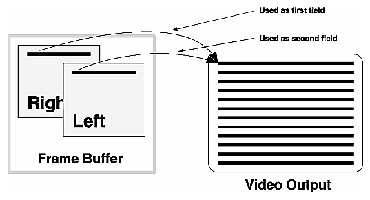
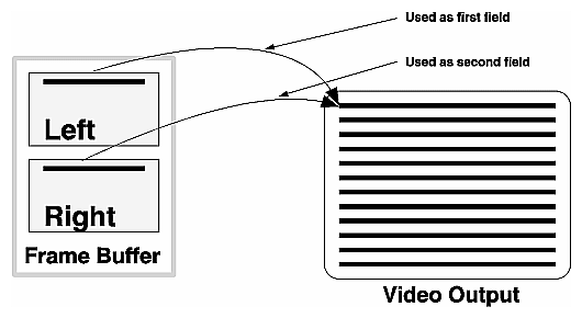
Contrast the multiple-field interlaced format with the way in which the graphics/video subsystem creates a multiple-field video for stereo display, shown in Figure 3-12. In the stereo video format, the frame is drawn twice as often as it would be for comparable monocular vision.
The difference between the two fields comes not from the architecture of the video frame (as was the case in “Interlaced Formats”), but from the frame buffer: the video frame draws each line—the same lines on the monitor for each field of the frame. However, for each field, the pixels fetched from the frame buffer differ slightly because a program draws each eye's buffer slightly differently, left or right.
In per-window stereo, each pixel in the frame buffer contains a different section for left and right eyes (you can think of this as two pixels stored in the same address).
Figure 3-12 shows the right buffer drawn first, the left buffer second. A different monitor might require the left buffer be drawn first.
Compare Figure 3-13 to that of Figure 3-12 describing Per-Window Stereo. The difference between these two stereo modes is relatively minor: full-screen stereo fetches its left and right pixels from different locations, the pixels in the upper part of the frame buffer making one eye, pixels in the lower part give the other eye.
This full-screen stereo mode also requires additional support. See XSGISetStereoMode(3X11).
The definition of the components of the video format can differ from one specification to another. For example, the PAL definition of the beginning of the frame is at the beginning of the vertical synchronization pulse; the definition for NTSC places the beginning of the frame at the first equalization pulse after the last line of active video (Report 624-4, Section 11A, XVIIth Plenary Assembly of the CCIR, Düsseldorf, 1990).
Confusing? Yes. But not problematic to the construction and analysis of the frame.
To solve this problem, the video format compiler declares a standard boundary for each component of the video frame. These boundaries are used irrespective of video format used.
Under some circumstances, you may need to convert from the standard used by a video format specification to the compiler's use. In the example above with the position of the beginning of frame of the NTSC and PAL video formats, the video format compiler uses the same definition as does PAL, with the start of the frame beginning at the vertical synchronization pulse. In this circumstance, the NTSC format adopts a slightly different definition.
The definition of each of the components of the horizontal line is in “The Horizontal Line”; the definition of the vertical components is in “The Vertical Interval”.
This section describes an artifact of the way video is created. This does not have much to do with video formats themselves.
Although video is considered in terms of pixels, it is often grouped into units of multiple pixels for handling in hardware. By grouping pixels, the video hardware deals with one of these groups of multiple pixels, not with individual pixels.
What is the consequence of this grouping? Although the pixels retain their individual identity from the frame buffer, the horizontal and vertical blanking intervals (see “The Horizontal Line” and “The Vertical Interval”) do not have the same flexibility: you cannot program, for example, a sync transition to occur on an arbitrary pixel boundary. Instead, these transitions can occur only at pixel positions that are on the boundaries of these groups. The quantizing effect forces the compiler to alter positions of some transitions.
For example, Figure 3-14 shows the quantization effect of an example hardware output device that has a pixel-to-clock ratio of 3:1 (three pixels per clock). The series of transitions labeled Specified shows the set of transitions as they might be specified to the compiler. Because the hardware can resolve transitions only every three pixels, the compiler will round the time of each transition to be that of the nearest clock transition. The result is shown in the set of transitions labeled Actual.
Some output hardware is fixed at only one ratio, while other hardware may support different quantization ratios based on the final frequency, optional attributes, or other characteristics. The release notes accompanying the video format compiler for your hardware will help you determine the quantization value you should expect. You can see the quantization value applied to your video format by using the -a ascii command-line option of the compiler.
