The guide describes the hardware architecture of the Origin family, and its specific implementations:
The entry-level Origin200™ system, consisting of a maximum of two towers (up to four processors) that can be linked together.
The deskside/rackmount Origin2000 system, presently consisting of from 1 to 32 processors (with potential future expansion to 128), housed in deskside and rackmount cabinets.
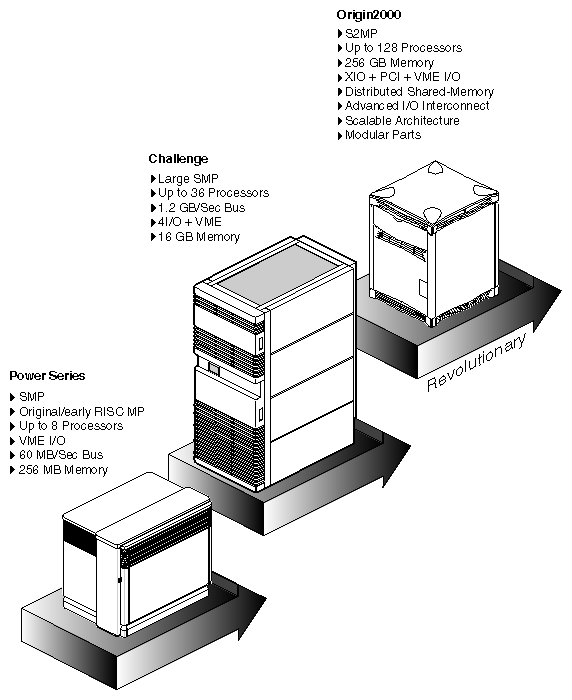
The Origin family is a revolutionary follow-on to the CHALLENGE®-class symmetric multiprocessing (SMP) system. It uses Silicon Graphics' distributed Scalable Shared-memory MultiProcessing architecture, called S2MP.
The development path Silicon Graphics' multiprocessor systems is shown in Figure 1-1.
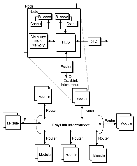
As illustrated in Figure 1-2, Origin2000 is a number of processing nodes linked together by an interconnection fabric. Each processing node contains either one or two processors, a portion of shared memory, a directory for cache coherence, and two interfaces: one that connects to I/O devices and another that links system nodes through the interconnection fabric.
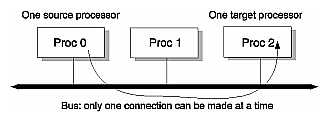
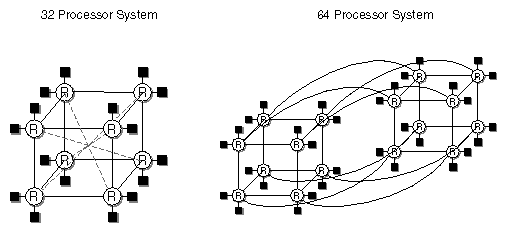
The interconnection fabric links nodes to each other, but it differs from a bus in several important ways. A bus is a resource that can only be used by one processor at a time. The interconnection fabric is a mesh of multiple, simultaneous, dynamically-allocable — that is, connections are made from processor to processor as they are needed — transactions. This web of connections differs from a bus in the same way that multiple dimensions differ from a single dimension: if a bus is a one-dimensional line, then the interconnection fabric is a multi-dimensional mesh.
As shown in Figure 1-3, a bus is a shared, common link that multiprocessors must contest for and that only a single processor can use at a time. The interconnection fabric allows many nodes to communicate simultaneously, as shown in Figure 1-4. (Each black box connected to a router (“R”) is a node that contains two R10000™ processors.) Paths through the interconnection fabric are constructed as they are needed by Router ASICs, which act as switches.
The Origin2000 system is said to be scalable, because it can range in size from 1 to 128 processors. As you add nodes, you add to and scale the system bandwidth. The Origin2000 is also modular, in that it can be increased in size by adding standard modules to the interconnection fabric. The interconnection fabric is implemented on cables outside of these modules.
The Origin family uses Silicon Graphics' S2MP architecture to distribute shared memory amongst the nodes. This shared memory is accessible to all processors through the interconnection fabric and can be accessed with low latency.
The next sections describe both the Origin200 system and the Origin2000 system.
The Origin200 system can consist of one or two towers. The maximum configuration of two towers is connected together by the CrayLink™ interconnection fabric (this is described earlier in this chapter). Each tower has the following:
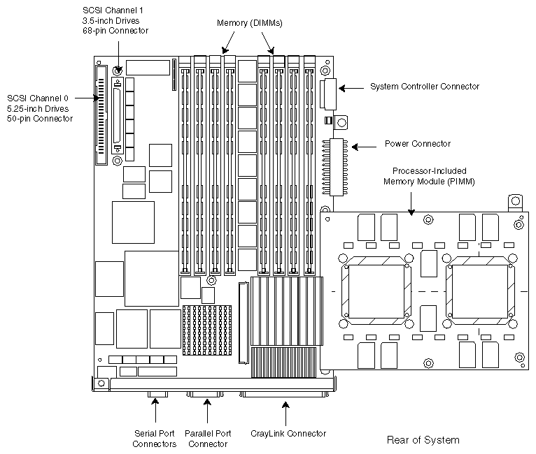
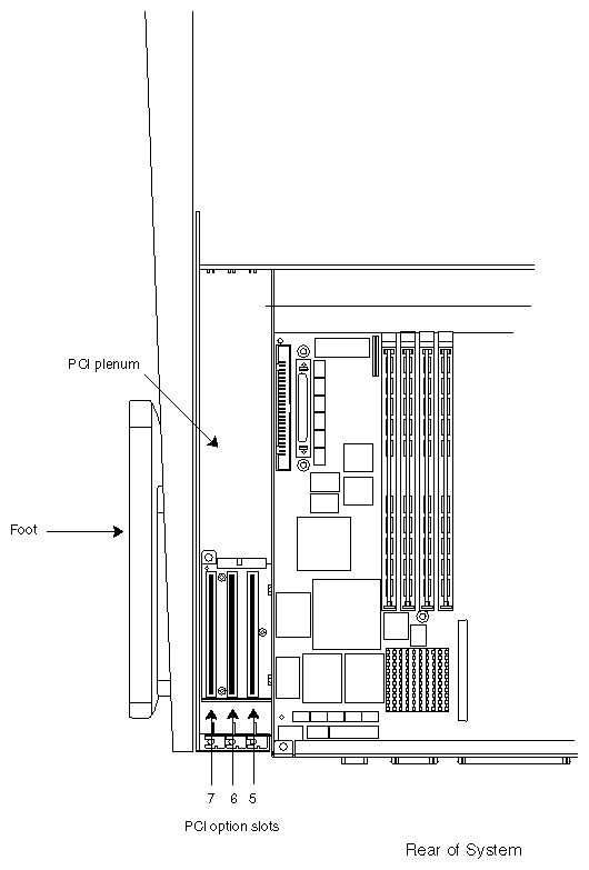
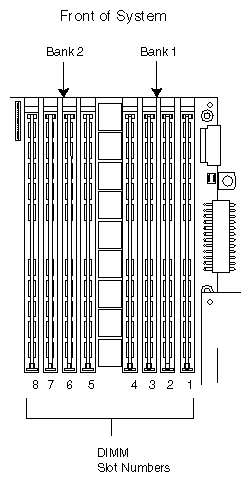
Locations of the mother and daughterboards are shown in Figure 1-5 and the locations of the PCI slots are shown in Figure 1-6. Figure 1-7 shows the layout of the memory DIMMs on the motherboard.
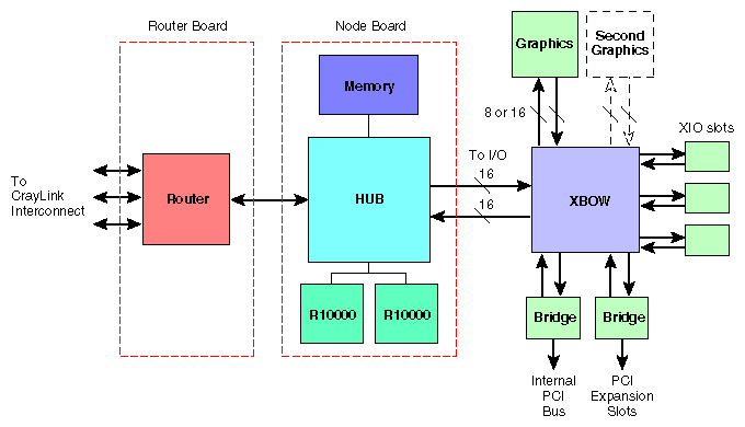
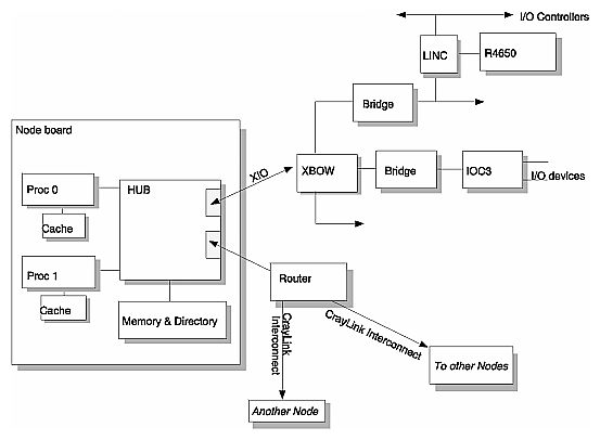
Figure 1-8 is a block diagram of an Origin2000 system showing the central Node board, which can be viewed as a system controller from which all other system components radiate.
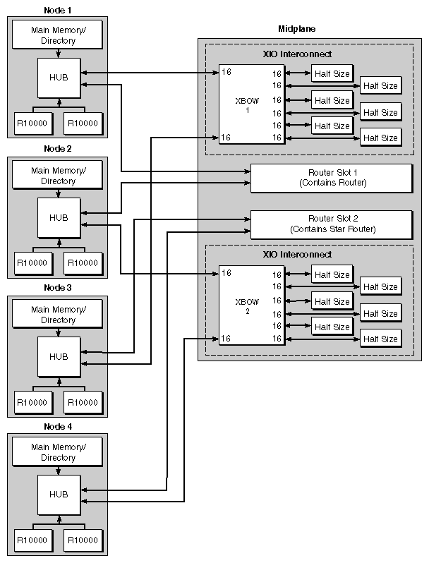
Figure 1-9 is a block diagram of a system with four Node boards; Nodes 1 and 3 connect to Crossbow (XBOW) 1, and Nodes 2 and 4 connect to Crossbow 2. Crossbow 1 connects to XIO boards 1 through 6 and Crossbow 2 connects to XIO boards 7 through 12.
An Origin2000 system has the following components:
These are linked as shown in Figure 1-8 and Figure 1-9, and all are described in this section.
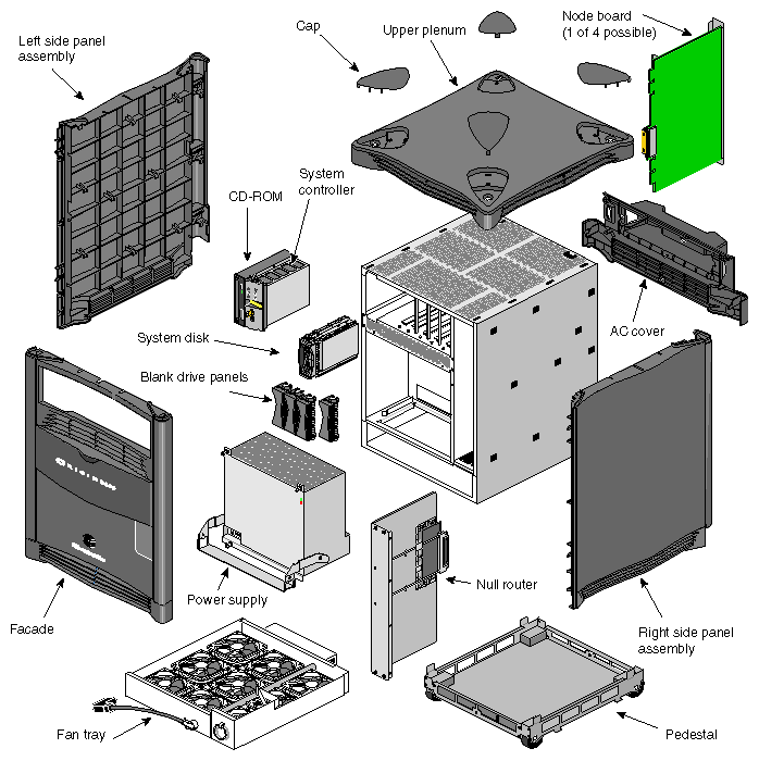
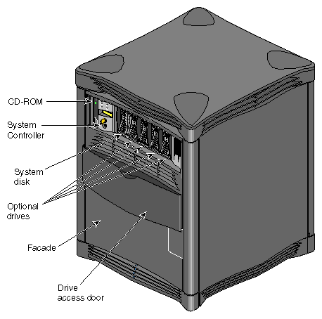
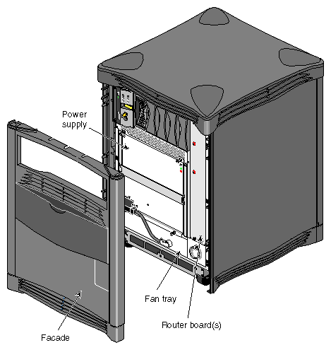
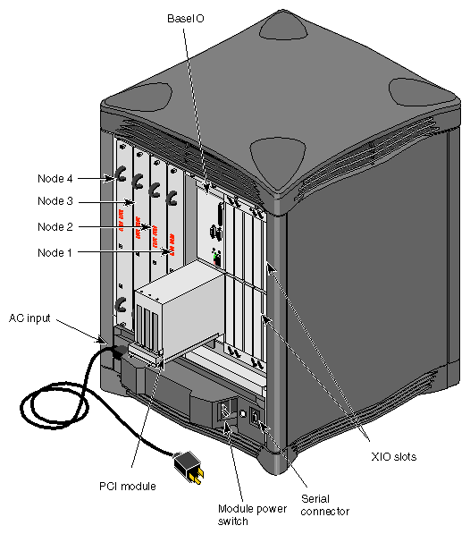
An exploded view of an Origin2000 deskside system is shown in Figure 1-10. A front view of the enclosed module is shown in Figure 1-11 and a front view with the facade removed is shown in Figure 1-12. A rear view of the deskside chassis, showing the Node and XIO board locations, is shown in Figure 1-13, and Figure 1-14 shows a block diagram of a basic Origin2000 system with a single node connected to XIO and the CrayLink Interconnect.
Origin2000 system uses the MIPS® R10000, a high-performance 64-bit superscalar processor which supports dynamic scheduling. Some of the important attributes of the R10000 are its large memory address space, together with a capacity for heavy overlapping of memory transactions — up to twelve per processor in Origin2000.
Each Node board added to Origin2000 is another independent bank of memory, and each bank is capable of supporting up to 4 GB of memory. Up to 64 nodes can be configured in a system, which implies a maximum memory capacity of 256 GB.
Origin2000 supports a number of high-speed I/O interfaces, including Fast, Wide SCSI, Fibrechannel, 100BASE-Tx, ATM, and HIPPI-Serial. Internally, these controllers are added through XIO cards, which have an embedded PCI-32 or PCI-64 bus. Thus, in Origin2000 I/O performance is added one bus at a time.
This ASIC is the distributed shared-memory controller. It is responsible for providing all of the processors and I/O devices a transparent access to all of distributed memory in a cache-coherent manner
This supplementary memory is controlled by the Hub. The directory keeps information about the cache status of all memory within its node. This status information is used to provide scalable cache coherence, and to migrate data to a node that accesses it more frequently than the present node.
This is a collection of very high speed links and routers that is responsible for tying together the set of hubs that make up the system. The important attributes of CrayLink Interconnect are its low latency, scalable bandwidth, modularity, and fault tolerance.
These are the internal I/O interfaces originating in each Hub and terminating on the targeted I/O controller. XIO uses the same physical link technology as CrayLink Interconnect, but uses a protocol optimized for I/O traffic. The Crossbow ASIC is a crossbar routing chip responsible for connecting two nodes to up to six I/O controllers.
The following characteristics make Origin2000 different from previous system architectures (the terms in italics are described in more detail throughout the remainder of this chapter):
Origin2000 is scalable.
Origin2000 is modular.
Origin2000 uses an interconnection fabric to link system nodes and internal crossbars within the system ASICs (Hub, Router, Crossbow).
Origin2000 has distributed shared-memory and distributed shared-I/O.
Origin2000 shared memory is kept cache coherent using directories and a directory-based cache coherence protocol.
Origin2000 uses page migration and replication to improve memory latency.
Scalability. Origin2000 is easily scaled by linking nodes together over an interconnection fabric, and system bandwidth scales linearly with an increase in the number of processors and the associated switching fabric. This means Origin2000 can have a low entry cost, since you can build a system upward from an inexpensive configuration.
In contrast, POWER CHALLENGE™ is only scalable in the amount of its processing and I/O power. The Everest interconnect is the E-bus, which has a fixed bandwidth and is the same size from entry-level to high-end.
Modularity. A system is comprised of standard processing nodes. Each node contains processor(s), memory, a directory for cache coherence, an I/O interface, and a system interconnection. Node boards are placed in both the Origin200 and Origin2000 systems, although they are not identical.
Due to its bus-based design, CHALLENGE is not as modular; there is a fixed number of slots in each deskside or rack system, and this number cannot be changed.
System interconnections. Origin2000 uses an interconnection fabric and crossbars. The interconnection fabric is a web of dynamically-allocated switch-connected links that attach nodes to one another. Crossbars are part of the interconnection fabric, and are located inside several of the ASICs — the Crossbow, the Router, and the Hub. Crossbars dynamically link ASIC input ports with their output ports.
In CHALLENGE, processors access memory and I/O interfaces over a shared system bus (E-bus) that has a fixed size and a fixed bandwidth.
Distributed shared-memory (DSM) and I/O. Origin2000 memory is physically dispersed throughout the system for faster processor access. Page migration hardware moves data into memory closer to a processor that frequently uses it. This page migration scheme reduces memory latency — the time it takes to retrieve data from memory. Although main memory is distributed, it is universally accessible and shared between all the processors in the system. Similarly, I/O devices are distributed among the nodes, and each device is accessible to every processor in the system.
CHALLENGE has shared memory, but its memory is concentrated, not distributed, and CHALLENGE does not distribute I/O. All I/O accesses, and those memory accesses not satisfied by the cache, incur extra latencies when traversing the E-bus.
Directory-based cache coherence. Origin2000 uses caches to reduce memory latency. Cache coherence is supported by a hardware directory that is distributed among the nodes along with main memory. Cache coherence is applied across the entire system and all memory. In a snoopy protocol, every cache-line invalidation must be broadcast to all CPUs in the system, whether the CPU has a copy of the cache line or not. In contrast, a directory protocol relies on point-to-point messages that are only sent those CPUs actually using the cache line. This removes the scalability problems inherent in the snoopy coherence scheme used by bus-based systems such as Everest. A directory-based protocol is preferable to snooping since it reduces the amount of coherence traffic that must be sent throughout the system.
CHALLENGE uses a snoopy coherence protocol.
Page migration and replication. To provide better performance by reducing the amount of remote memory traffic, Origin2000 uses a process called page migration. Page migration moves data that is often used by a processor into memory close to that processor.
CHALLENGE does not support page migration.
Origin2000 scalability and modularity allow one to start with a small system and incrementally add modules to make the system as large as needed. An entry-level Origin20000 module can hold from one to four MIPS R10000 processors, and a Origin2000 deskside module can hold from one to eight R10000 processors. A series of these deskside modules can be mounted in racks, scaling the system up to the following maximum configuration:
128 processors
256 GB of memory
64 I/O interfaces with 192 I/O controllers (or 184 XIO and 24 PCI-64)
128 3.5-inch Ultra-SCSI devices and 16 6.25-inch devices
As one adds nodes to the interconnection fabric, bandwidth and performance scale linearly without significantly impacting system latencies. This is a result of the following design decisions:
replacing the fixed-size, fixed-bandwidth bus of CHALLENGE with the scalable interconnection fabric whose bisection bandwidth (the bandwidth through the center of CrayLink Interconnect) scales linearly with the number of nodes in the system
reducing system latencies by replacing the centrally-located main memory of CHALLENGE with the tightly-integrated but distributed shared-memory S2MP architecture of Origin2000.
Origin2000 replaces CHALLENGE's shared, fixed-bandwidth bus with the following:
a scalable interconnection fabric, in which processing nodes are linked by a set of routers
crossbar switches, which implement the interconnection fabric. Crossbars are located in the following places:
within the Crossbow ASIC connecting the I/O interfaces to the nodes
within the Router ASIC forming the interconnection fabric itself,
within the Hub ASIC which interconnects the processors, memory, I/O, and interconnection fabric interfaces within each node.
These internal crossbars maximize the throughput of the major system components and concurrent operations.
Origin2000 nodes are connected by an interconnection fabric. The interconnection fabric is a set of switches, called routers, that are linked by cables in various configurations, or topologies. The interconnection fabric differs from a standard bus in the following important ways:
The interconnection fabric is a mesh of multiple point-to-point links connected by the routing switches. These links and switches allow multiple transactions to occur simultaneously.
The links permit extremely fast switching. Each bidirectional link sustains as much bandwidth as the entire Everest bus.
The interconnection fabric does not require arbitration nor is it as limited by contention, while a bus must be contested for through arbitration.
More routers and links are added as nodes are added, increasing the interconnection fabric's bandwidth. A shared bus has a fixed bandwidth that is not scalable.
The topology of the CrayLink Interconnect is such that the bisection bandwidth grows linearly with the number of nodes in the system.
The interconnection fabric provides a minimum of two separate paths to every pair of Origin2000 nodes. This redundancy allows the system to bypass failing routers or broken interconnection fabric links. Each fabric link is additionally protected by a CRC code and a link-level protocol, which retry any corrupted transmissions and provide fault tolerance for transient errors.
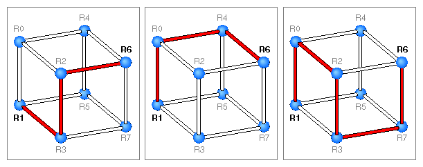
Earlier in this chapter, Figure 1-3 and Figure 1-4 showed how an interconnection fabric differs from an ordinary shared bus. Figure 1-15 amplifies this difference by illustrating an 8-node hypercube with its multiple datapaths. Simultaneously, R1 can communicate with R0, R2 to R3, R4 to R6, and R5 to R7, all without having to interface with any other node.
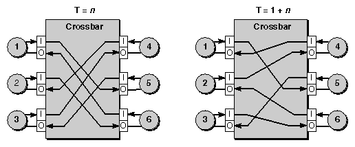
Several of the ASICs (Hub, Router, and Crossbow) use a crossbar for linking on-chip inputs with on-chip output interfaces. For instance, an 8-way crossbar is used on the Crossbow ASIC; this crossbar creates direct point-to-point links between one or more nodes and multiple I/O devices. The crossbar switch also allows peer-to-peer communication, in which one I/O device can speak directly to another I/O device.
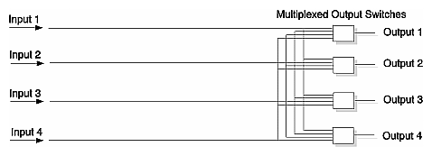
The Router ASIC uses a similar 6-way crossbar to link its six ports with the interconnection fabric, and the Hub ASIC links its four interfaces with a crossbar. A logical diagram of a 4-way (also referred to as four-by-four, or 4 x 4) crossbar is given in Figure 1-16; note that each output is determined by multiplexing the four inputs.
Figure 1-17 shows a 6-way crossbar at work. In this example, the crossbar connects six ports, and each port has an input (I) and an output (O) buffer for flow control. Since there must be an output for every input, the six ports can be connected as six independent, parallel paths. The crossbar connections are shown at two clock intervals: Time=n, and Time=n+1.
At clock T=n, the ports independently make the following parallel connections:
from port 1 to port 5
from port 2 to port 6
from port 3 to port 4
from port 4 to port 2
from port 5 to port 3
from port 6 to port 1
Figure 1-17 shows the source (Input) and target (Output) for each connection, and arrows indicate the direction of flow. When a connection is active, its source and target are not available for any other connection over the crossbar.
At the next clock, T=n+1, the ports independently reconfigure themselves[1] into six new data links: 1-to-5, 2-to-4, 3-to-6, 4-to-1, 5-to-3 and 6-to-2. At clock intervals, the ports continue making new connections as needed. Connection decisions are based on algorithms that take into account flow control, routing, and arbitration.
Origin2000 memory is located in a single shared address space. Memory within this space is distributed amongst all the processors, and is accessible over the interconnection fabric. This differs from an CHALLENGE-class system, in which memory is centrally located on and only accessible over a single shared bus. By distributing Origin2000's memory among processors memory latency is reduced: accessing memory near to a processor take less time than accessing remote memory. Although physically distributed, main memory is available to all processors.
I/O devices are also distributed within a shared address space; every I/O device is universally accessible throughout the system.
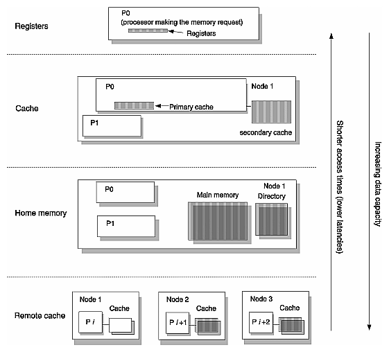
Memory in Origin2000 is organized into the following hierarchy:
At the top, and closest to the processor making the memory request, are the processor registers. Since they are physically on the chip they have the lowest latency — that is, they have the fastest access times. In Figure 1-18, these are on the processor labelled P0.
The next level of memory hierarchy is labelled cache. In Figure 1-18, these are the primary and secondary caches located on P0. Aside from the registers, caches have the lowest latency in Origin2000, since they are also on the R10000 chip (primary cache) or tightly-coupled to its processor on a daughterboard (secondary cache).
The next level of memory hierarchy is called home memory, which can be either local or remote. The access is local if the address of the memory reference is to address space on the same node as the processor. The access is remote if the address of the memory reference is to address space on another node. In Figure 1-18, home memory is the block of main memory on Node 1, which means it is local to Processor 0.
The next level of memory hierarchy consists of the remote caches that may be holding copies of a given memory block. If the requesting processor is writing, these copies must be invalidated. If the processor is reading, this level exists if another processor has the most up-to-date copy of the requested location. In Figure 1-18, remote cache is represented by the blocks labelled “cache” on Nodes 2 and 3.
Caches are used to reduce the amount of time it takes to access memory — also known as a memory's latency — by moving faster memory physically close to, or even onto, the processor. This faster memory is generally some version of static RAM, or SRAM.
The DSM structure of Origin2000 also creates the notion of local memory. This memory is close to the processor and has reduced latency compared to bus-based systems, where all memory must be accessed through a shared bus.
While data only exists in either local or remote memory, copies of the data can exist in various processor caches. Keeping these copies consistent is the responsibility of the logic of the various hubs. This logic is collectively referred to as a cache-coherence protocol, described in Chapter 2.
Three types of bandwidth are cited in this manual:
Peak bandwidth, which is a theoretical number derived by multiplying the clock rate at the interface by the data width of the interface.
Sustained bandwidth, which is derived by subtracting the packet header and any other immediate overhead from the peak bandwidth. This best-case figure, sometimes called Peak Payload bandwidth, does not take into account contention and other variable effects.
Bisection bandwidth, which derived by dividing the interconnection fabric in half, and measuring the data rate across this divide. This figure is useful for measuring data rates when the data is not optimally placed.
Table 1-1 gives a comparison between peak and sustained data bandwidths at the Crosstalk and interconnection fabric interfaces of the Hub.
Table 1-1. Comparison of Peak and Sustained Bandwidths
|
| Peak Bandwidth, | Sustained Bandwidth |
|---|---|---|---|
Processor | Unidirectional | 800 MB |
|
Memory | Unidirectional | 800 MB |
|
Interconnection Fabric | Full duplex | 1.6 GB | 1.28 GB |
| Half duplex | 800 MB | 711 MB |
Crosstalk | 8-bit Full duplex | 800 MB | 640 MB |
| 8-bit Half duplex | 400 MB | 355 MB |
| 16-bit Full duplex | 1.6 GB | 1.28 GB |
| 16-bit Half duplex | 800 MB | 711 MB |
Table 1-2 lists the bisection bandwidths of various Origin2000 configurations both with and without Xpress Links.
Table 1-2. System Bisection Bandwidths
System Size | Sustained Bisection Bandwidth | Sustained Bisection Bandwidth |
|---|---|---|
8 | 1.28 GB per second [1.6 GB] | 2.56 GB per second [3.2 GB][a] |
16 | 2.56 GB per second [3.2 GB] | 5.12 GB per second [6.4 GB] |
32 | 5.12 GB per second [6.4 GB] | 10.2 GB per second [12.8 GB] |
64 | 10.2 GB per second [12.8 GB] | N/A |
128 | 20.5 GB per second [25.6 GB] | N/A |
[a] Using a Star Router | ||
Table 1-3 lists the bandwidths of Ultra SCSI and FibreChannel devices.
Table 1-3. Peripheral Bandwidths
Peripheral | Bandwidth |
|---|---|
Ultra SCSI | 40 MB per second |
FibreChannel | 100 MB per second |
