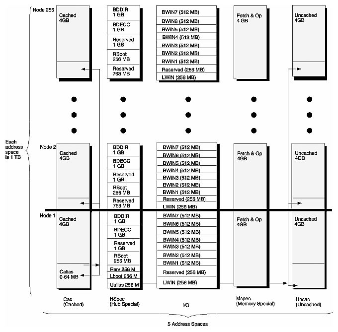
Figure 2-1 illustrates M Mode physical address space. There are five different address spaces:
All spaces but Cac are uncached spaces.
Each of these spaces are 1 TB, within which an M Mode node is allocated 4 GB. As shown in Figure 2-1, the entire 1 TB range of each address space is divided equally among the 256 nodes (256*4 GB = 1 TB).
The first of these spaces, Cac, is described in the next section. The four remaining uncached spaces are described in succeeding sections.
The four uncached spaces are accessed by using uncached operations, and are differentiated by encodings of the 2-bit Uncached Attribute field of the EntryLo0 and EntryLo1 registers on the R10000 processor. These four spaces and their Uncached Attribute field encodings are listed in Table 2-1:
Table 2-1. Uncached Attribute Field Encoding
UC Field Encoding | Space | Name |
|---|---|---|
00 | HSpec | Hub Special Space |
01 | IO | I/O Space |
10 | Mspec | Memory Special Space |
11 | Uncac | Uncached Space |
All cacheable loads and stores operate in the Cac physical address space. Secondary cache lines are 128 bytes.
The Cac space is flat, except for the lowest portion of Cac space memory, which may be used as a local alias. This lowest portion is referred to as Calias. It may range in size from 0 to 64 MB, as determined by bit settings in the CALIAS_SIZE register in the Hub ASIC. Encodings of the CALIAS_SIZE register are shown in Table 2-2.
Table 2-2. Calias_Size Register Encoding
Register Entry |
| Register Entry |
|
|---|---|---|---|
0000 | 0 bytes | 1000 | 512 KB |
0001 | 4 KB | 1001 | 1 MB |
0010 | 8 KB | 1010 | 2 MB |
0011 | 16 KB | 1011 | 4 MB |
0100 | 32 KB | 1100 | 8 MB |
0101 | 64 KB | 1101 | 16 MB |
0110 | 128 KB | 1110 | 32 MB |
0111 | 256 KB | 1111 | 64 MB |
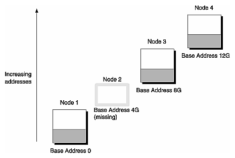
With Calias set to 0, M Mode memory accesses to the Cac space map from node to node in 4 GB increments, as shown in Figure 2-2:
accesses to physical address 0 map to the base address of Node 1 (address 0 GB)
accesses to physical address 4G map to the base address of Node 2 (address 4 GB)
accesses to physical address 8G map to the base address of Node 3 (address 8 GB)
accesses to physical address 12G map to the base address of Node 4 (address 12 GB)
And so on.
If a particular node is missing, it leaves a gap in the address map and any attempted access to the missing address space returns an address error.
Calias memory space for all nodes is only accessible by the local processor, at physical address 0 up to Calias size.
The uncached space designated when Uncached Attribute=0 is the Hub Special space, or HSpec space. It is divided into the following subspaces:
As shown in Figure 2-1, the uppermost 1 GB of each node's HSpec space is a backdoor access to the directory entries and protection information, labelled the BDDir space. Backdoor access is available through this separate memory space for diagnostics.
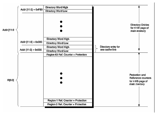
As shown in Figure 2-3, directory entries are indexed by address bits A[11:00] and protection information indexed by region bits R[5:0]. There is a directory entry for each 4 KB page in the node's main memory, and an Origin system has 64 regions, one for each two-processor node. These directory entries and regions are grouped together as 128 consecutive words.
The directory comes in two widths, extended and regular.
The width of the regular directory is 16 bits. For configurations up to 32 processors (32P), regular directory memory is included in the main memory DIMMs.
The width of the extended or premium directory is 48 bits. For configurations larger than 32P, an extended directory memory must be used. The extended directory is contained in dedicated directory DIMMs which are installed in dedicated slots on the Node board.
Only doubleword reads are allowed from the BDDir space.
The directory word contains an ECC code, and a BDDir read returns both the directory information and this ECC code. Read data is carried on bits [47:0] for the extended directory, on bits [15:0] for the regular directory.
Only doubleword writes are allowed to the BDDir space.
Backdoor directory writes contain the ECC code to be written. Write data for an extended directory is on bits [47:0], and on bits [15:0] for a regular directory.
If bit 63 of the write data is cleared (a zero), the ECC value generated by the Hub chip is written into memory. If bit 63 is set (a one), the ECC write data is used in the backdoor write. Bit 63 should only be set to force an incorrect ECC value into the directory.
The HSpec address A[39:32], 1, 1, A[31:12], 1, A[11:7], DWBit, 000 is used to index the directory entry for a given 128-byte cache line A[39:7] in M Mode. This mapping is shown in Figure 2-4.
When a system has 128 or fewer processors, a region is defined as a single node. If a system has more than 128 CPUs, a region consists of 8 nodes.
Accesses to the protection and page reference count for a given region, R[5:0], and the page A[39:12], in M Mode, are made using the Hspec address bits A[39:32], 1, 1, A[31:12], 0, R[5:0], 000. This mapping is shown in Figure 2-5.
On backdoor writes to the protection and page reference entries, bit 63 is ignored, since these entries do not use ECC.
As shown in Figure 2-1, the 1 GB address space below BDDir is the Backdoor ECC space, BDECC. Memory ECC entries are read from and written to this space.
Accessing the backdoor ECC for a given address A[39:3] is done by mapping the following HSpec address: A[39:32], 1, 0, A[31:5], 0/1, A[4:3].
A[4:3] is an endianness indicator; for Little Endian, A[4:3] is replaced with its complement. Backdoor ECC mapping is shown in Figure 2-6.
A read of the BDECC retrieves the 8-bit ECC codes for 4 consecutive doublewords. Reads can be byte, halfword, or word operations. 64-bit doubleword operations are supported by the hardware, but simply return the same data duplicated on the high and low 32 bits.
The hardware does not use address bit 2 when designating the ECC values to be read or written; this means the 32-bit data can be accessed with two addresses, one with bit 2 set and one with bit 2 clear.
All nodes have an Rboot space allocated, however only Node 1 has an LBoot space. Refer to Figure 2-1 for the locations of LBoot and RBoot space.
Accesses to LBoot space map to the node's local boot PROM and any other devices that are associated with the local boot PROM. The R10000 boot vector resides in LBoot space.
The 256 MB RBoot space is located at an offset of 768M within each node. This space is an alias for the LBoot PROM of that node, and is intended to be used for diagnostics by remote processors.
The 1 MB Flash PROM is accessible in both the LBoot and RBoot spaces. The Hub allows three operations to the Flash PROM:
doubleword (64-bit) reads
word (32-bit) reads
doubleword writes (for which only the lower byte is used)
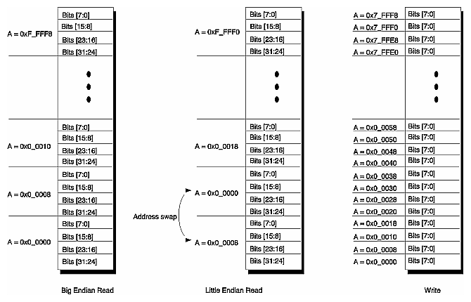
The Hub sequences reads of the PROM in Big Endian order. Doubleword reads are the same for both Big and Little Endian modes, but the layout of the FPROM is different for word reads in Big Endian and Little Endian modes, as shown in Figure 2-7. In Little-endian mode, all word pairs are swapped. The Hub sequences reads of the Flash PROM in Big Endian mode only.
The Hub does not decode the LBoot or RBoot space for address errors, so the FPROM can be accessed in any window that is mod 0 of the FPROM size.
Read and write images of the FPROM are shown in Figure 2-7.
FPROM Reads
Reading the FPROM requires a 1 MB window in LBoot or RBoot space.
FPROM Writes
Writing the 1-MB FPROM requires an 8 MB window in LBoot or RBoot space, since writes are doubleword operations with respect to the processor, but only byte operations into the FPROM.[2]
With the exception of Node 1, the lowest 768 MB of each node's HSpec space is reserved; refer to Figure 2-1 for an illustration of this mapping.
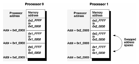
In Node 1, the lowest 256 MB of the HSpec space is used as an alias for uncached access to low local memory. This uncached alias space is labelled Ualias, and the low local memory it aliases is in Uncac space (the Uncached Attribute=112).
Similar to Calias space, an access by Node 1 to Ualias indexes the lowest 256 MB of its Uncac space. An access by Node 2 to Ualias addresses the lowest 256 MB of its Uncac, which has a base address of 4GB. An access by Node 3 to Ualias addresses the lowest 256 MB of its Uncac, which starts at 8GB.
However, Ualias differs from Calias in regards to the two R10000 processors, processor 0 (A) and processor 1 (B), on its Hub.
For processor 0 (A), the address mapping is done as normal: accesses to address 0 map to address 0, address 64K maps to 64K.
However, when processor 1 (B) accesses the lowest 64K, its access starts at base address 64K, and when it accesses the next 64K, its access starts at base address 0K; that is, the lowest and next lowest 64 KB pages are flipped.
The vector for the cache error handler is located in Ualias space. The address swapping described above provides the cache error handler of each processor with an individual portion of memory it can access relative to r0, to store processor state. The swapping is shown in Figure 2-8.
IO space is accessed by an uncached operation with an Uncached Attribute of 012 (refer to Table 2-1 for the Uncached Attributes).
Each node's portion of the IO space is divided into seven 512-MB subspaces and two 256 MB subspaces, as shown in Figure 2-1.
The lowest 256 MB subspace is referred to as a “little window” (LWin) into IO space. LWin consists of sixteen 16-MB direct-mapped windows, one for each of the 16 XIO devices that can attach to Node (16*16 MB = 256 MB).
The next highest 256 MB subspace is reserved, and aliases to LWin space.
The remaining seven 512-MB spaces within IO are referred to as “big windows,” and are labelled BWin1 through BWin7. Each BWin[7:1] provides a 512 MB window that can be mapped to a 512 MB-aligned block of any I/O device's address space.
Uncached operations with an Uncached Attribute of 102 (refer to Table 2-1 for a list of Uncached Attributes) perform fetch-and-op operations on the memory space referred to as memory special, or MSpec. Any page used for a fetch-and-op cannot also be used for a regular cached access. The backing store for MSpec is regular memory.
As shown in Figure 2-1, MSpec is a flat address space.
Uncached operations with an Uncached Attribute of 112 (refer to Table 2-1 for a list of Uncached Attributes) perform uncached reads and writes of the memory referred to as uncached, or Uncac. As shown in Figure 2-1, Uncac is a flat address space.
