The OCTANE Personal Video board makes it possible to use your OCTANE workstation for video-based operations, such as
capturing the screen display: recording directly to disk any portion of the screen, from the full 1280 x 1024 resolution down to 2 pixels by 2 lines, for editing with bundled media editing tools or converting to standard NTSC- or PAL-encoded video
writing or using custom video applications
using applications included with the OCTANE workstation:
videoconferencing, using the O2Cam digital camera and the InPerson videoconferencing software for real-time group collaboration
Web authoring, using video compression algorithms implemented through software and the Web-based authoring tool suite included with the OCTANE system for distributing video via the World Wide Web
This chapter introduces
| Note: For an introduction to video, see the latest version of the Digital Media Programming Guide (007-1799-060 or later). |
This section explains
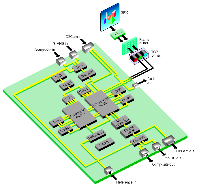
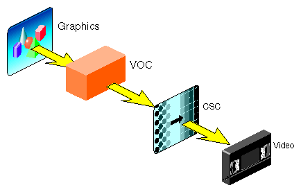
The OCTANE Personal Video option supports 1280 x 1024 at 50 Hz, 60 Hz, and 72 Hz. Input speed is limited by the pixel clock and input to the video output controller (VOC). The VOC receives the complete graphics stream as input; it can select all or a portion of the screen to resize and fit into a standard video raster.
The section “OCTANE Personal Video Software Model” explains how the board looks to the software.
Figure 1-1 diagrams the OCTANE Personal Video board.
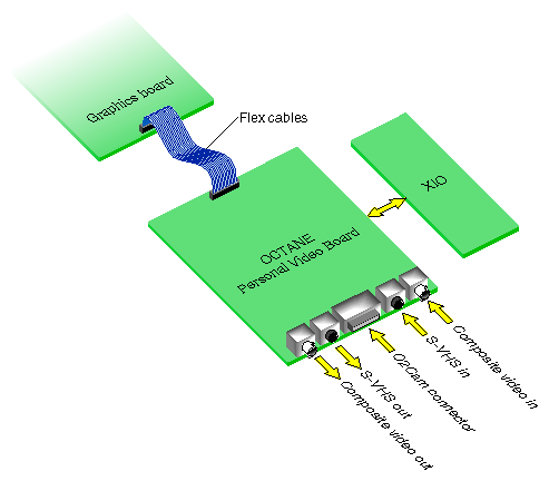
Figure 1-2 shows OCTANE Personal Video option connections to OCTANE graphics and connectors.
All graphics data comes through three dedicated internal flex cables connected to OCTANE graphics. Through connectors on the OCTANE Personal Video board itself, you can
send and receive live analog video, either S-Video or composite; you can software-select between the 525/60 NTSC and 625/50 PAL television standards
receive component digital video from any serial CCIR-601/SMPTE-259M-compliant device
send Silicon Graphics component digital video from any serial CCIR-601/SMPTE-259M-compliant device
receive live video from the O2Cam digital camera, which you can convert to CCIR601 with a third-party adapter
pass through audio from the O2Cam digital camera
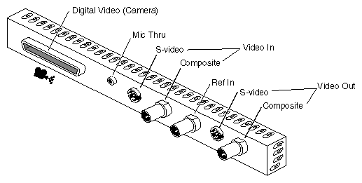
Figure 1-3 shows the connectors.
Table 1-1 summarizes board connectors.
Table 1-1. OCTANE Personal Video Connectors
Input | Output | Format |
|---|---|---|
Composite | Composite (single-channel video out) | BNC (75-ohm terminated) |
S-Video (single-channel video in) | S-Video (single-channel video out) | 4-pin mini-DIN |
Composite locking reference | N/A | BNC (75-ohm terminated) |
N/A | Audio: microphone through | 3.5-mm jack |
Silicon Graphics digital video (O2Cam digital camera) | Silicon Graphics digital video, with optional third-party devices connected | 68-pin D connector |
The board can genlock to external reference, O2 video, or Internal Video Sync. The sources for external reference are reference, composite video, and S-VHS video. The lock is color-frame accurate with respect to reference or composite video. Other important signals (reset, power rails, and so on) come from the board connection at the XIO slot.
For hardware details, including cabling information, see the OCTANE Personal Video Installation Guide.
The OCTANE Personal Video board can capture video from four sources:
composite video, digitized and decoded into the nonsquare pixel YUV format
S-VHS video, digitized into standard YUV format
O2Cam connector (digital): parallel input as YUV (D1)
The O2Cam connector can also be used for parallel D1 output.
graphics signals encoded in 24-bit RGB
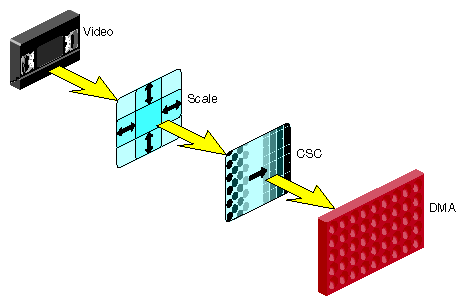
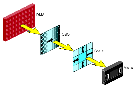
Video input processing captures input from one or more of these sources and transfers it to memory. During capture, you can scale (reduce, or minify) the image horizontally and vertically, such as for aspect ratio correction. The scaler is a YUV device only.
You can also color-space convert the image (CSC). The color-space converters allow transformation from YUV to RGB or from RGB to YUV.
Finally, you can DMA the image into memory; the board supports two DMA channels. Figure 1-4 diagrams the processing path.
Video output takes an image from memory and converts it into video, or performs the print-to-video process. Output video sources are memory, graphics (VOC), or video in (analog or digital). From memory, the board can process 8-bit YUV 422 or 24-bit RGB. (Although you can transfer 10- bit YUV, the processing path is only 8 bits wide.) If required, you can color-space convert the signal into the YUV 422 format.
After color-space conversion, the signal can go into a sampling rate converter, which scales a square-pixel image into a nonsquare-pixel image. The encoder is a nonsquare encoder; it expects 720 pixels per line. This conversion might be necessary because the video encoder operates on nonsquare pixels only; it does not directly accept square-pixel data. This filter is explained further in “Square-to-Nonsquare Pixel Filter,” later in this section.
Figure 1-5 diagrams the processing path of the output block.
The scaler scales down horizontally and vertically only (no upscaling).
Figure 1-6 diagrams the processing path using graphics as the video source.
The OCTANE Personal Video option supports
Internal Video Sync: a synchronization signal produced or consumed by some audio and video devices
This signal is explained in Chapter 2, “Setting Up Your VL Application.”
output subcarrier horizontal phase (SCH): subcarrier phase can be adjusted through software
coarse H: window-controlled coarse horizontal timing
color-space conversion: RGB-to-YUV and YUV-to-RGB conversion
OCTANE Personal Video color-space conversion is explained in “VL_COLORSPACE,” in Chapter 3, and Appendix D, “OCTANE Personal Video Color-Space Conversions.”.
digital dither filter to reduce artifacts (a bypassable filter)
square-to-nonsquare pixel conversion
Most applications native to the computing environment work in the square-pixel aspect ratio. However, professional video applications require nonsquare pixels, which preserve the correct aspect ratio.
The OCTANE Personal Video board can process video in square-pixel format. For optimum video quality, however, it outputs only nonsquare pixels. To accommodate both environments, the board includes a bypassable square-to-nonsquare pixel filter that operates on video.
Square-pixel NTSC has 640 active pixels per line, based on a sample clock of 12.2727 MHz. Square pixel PAL has 768 pixels per line, based on a sample clock of 14.75 MHz. Nonsquare pixel NTSC and PAL both have 720 pixels per line, based on a sample clock of 13.5 MHz. Thus, in the horizontal direction, the filter must decimate in PAL and interpolate in NTSC. (For simplification, the vertical scale is not considered.)
The OCTANE Personal Video board utilizes timing signals from three kinds of sources:
free run (default)
Internal Video Sync, from another producer of this signal
another external reference signal, such as from an analog reference, the O2Cam digital camera, or input video
The board can produce the Internal Video Sync signal.
The Video Library provides a software interface to the OCTANE Personal Video board, enabling applications to
display live video in a window
capture live video to system memory
encode graphics to video in real time
produce high-quality full-rate video output
The Video Library (VL) is a collection of device-independent and device-dependent C language calls for Silicon Graphics workstations equipped with video options. The VL provides generic video tools, including simple tools for importing and exporting digital data to and from Silicon Graphics systems, as well as to and from third-party video devices that adhere to the Silicon Graphics architectural model for video devices. Video tools are described in the Media Control Panels User's Guide; similar applications are supplied in source-code form as examples in the directories /usr/share/src/dmedia/video/vl and /usr/share/src/dmedia/video/vl/OpenGL.
The VL works with other Silicon Graphics libraries, such as OpenGL. The VL does not depend on the X Window System, but you can use X Window System libraries or toolkits to create a windowing interface.
The VL allows programs to get events 60 times per second on a quiescent system; it also enables programs to share resources or to gain exclusive use of resources. It supports input and output of video data to or from locked-down memory at the nominal frame rate. The VL provides an API that enables applications to capture or play back video from system memory.
The OCTANE Personal Video board software includes a graphical user interface, /usr/sbin/vcp. See the OCTANE Personal Video Installation Guide for how to use this panel with the OCTANE Personal Video option.
This section describes features of these VL system components and tools:
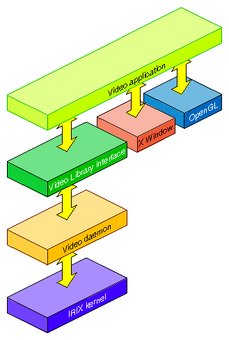
Figure 1-7 diagrams the interaction between the VL, the video daemon, the kernel, the hardware, and the X Window System server.
The VL communicates with the IRIX kernel for device initialization, vertical retrace, setup, and maintenance of any device-supported direct memory access (DMA). See Chapter 1 of the Digital Media Programming Guide for more information on interfacing to other libraries.
Besides these components, the VL includes a collection of applications that support device configuration and control setting and retrieval, generic tools that display video on a workstation, and video control panels.
The video daemon /usr/etc/videod, which has device-dependent and device-independent portions, handles video device management and status information.
Management that the video daemon performs includes
multiple client access to multiple devices
The library supports connections from multiple client applications and manages their access to a limited number of video devices.
dispatching events
As events are handled and noted by devices, the daemon notifies applications that have expressed interest in those events.
handling events
As events are generated by the various devices, the daemon initiates any action required by an event before it hands the event off to interested applications.
maintaining exclusive use
Types of data or control usage for video clients in a Video Library application are Done Using, Read-only, Lock, and Shared. These usage levels apply only to write access on controls, not read access. Any application can open and read the control's values at any time.
client cleanup on exit
When a client exits or is terminated abnormally, its connection to the daemon is broken; the daemon performs any cleanup required of the system. Any exclusive-use modes that have been set are cleared; interested clients are notified that the device is no longer in exclusive use. Controls set by the client might persist, but are not guaranteed to remain after the client closes the connection.
Status information for which the video daemon is responsible includes
system status of video devices
The video devices installed in a system can be queried as to availability and control status.
video positioning (offset) information
control setting and retrieval
Device-independent and device-dependent controls are set and retrieved through the video daemon.
The generic video tools include
The vlinfo, vidtomem, and memtovid tools are command-line tools. In addition to their reference pages, these tools have explanations in the Media Control Panels User's Guide. Similar applications are supplied in source-code form as examples in the directories /usr/share/src/dmedia/video/vl and /usr/share/src/dmedia/video/vl/OpenGL.
The client library is /usr/lib/libvl.so. The header files for the VL are in /usr/include/dmedia. The header file for the VL, vl.h, contains the main definition of the VL API and controls. The header file for OCTANE Personal Video is /usr/include/dmedia/vl_evo.h (linked to /usr/include/vl/dev_evo.h).
The VL recognizes these classes of objects:
devices, each including sets of nodes
A video device can be internal, such as the OCTANE Personal Video board, or external, such as a videotape recorder connected to the board.
events, for monitoring video I/O status
controls, or parameters, that modify how data flows through nodes; for example:
video device parameters, such as blanking width, gamma value, horizontal phase, sync source
video data capture parameters
buffers: for sending video data to and receiving video data from host memory
Central concepts for VL are node and path. This section explains
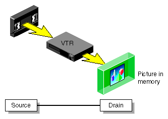
The node is an endpoint or internal processing element of the path, such as a video source like a VTR, video drain (such as to memory or a video output), or a device (video).
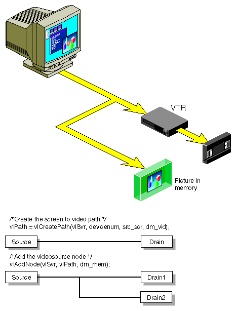
The path is an abstraction for a way of moving data around. A path is a set of nodes with video routes (connections) between the ports on the nodes. A path defines the useful connections between video sources and video drains. Figure 1-8 shows a simple path in which a frame from a videotape is captured to memory.
Figure 1-9 shows a more complex path with two video drains: a frame from a workstation window is captured to memory and sent to video output simultaneously. This path is set up in stages.
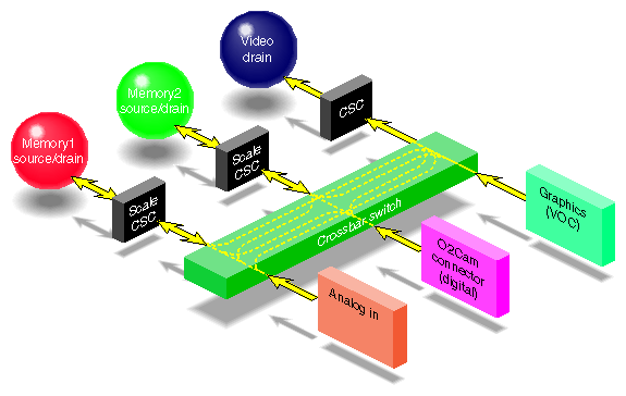
Figure 1-10 diagrams how the OCTANE Personal Video board looks to software.
Memory nodes appear as both source and drains. These nodes cannot be both at the same time; source and drain modes are mutually exclusive.
The board's crossbar switch allows any source to connect to any drain. Multiple connections can be made simultaneously. For example, the board can capture video and transfer it to memory simultaneously; it can capture video and transfer it to one memory drain in YUV format and the other in RGB format, all simultaneously.
The OCTANE Personal Video board translates video signals into a form usable by the OCTANE workstation. It also does the reverse, translating graphics from the OCTANE display into video signals. Table 1-2 summarizes the formats that the OCTANE Personal Video board supports
Table 1-2. Video Formats for OCTANE Personal Video Memory Nodes
Format | Signal |
|---|---|
Digital component YCrCb serial (VL_FORMAT_DIGITAL_COMPONENT_SERIAL) | YCrCb 4:2:2 serial digital signal with 8-bit words. Component ranges are 16 to 235. Conforms to the CCIR-601 specification. |
SMPTE YUV (VL_FORMAT_SMPTE_YUV) | Contains YUV components in the range 1-254; superblack and superwhite values can be present. |
Digital component RGB serial | Dual-link RGBA signal with GBR 4:2:2 (b0, g0, r0, g1, b2, g2, r2...) on the first link and ABR 4:2:2 (b1, a0, r1, a1, b3, a2, r3...) on the second link. Component ranges are 16 to 235 (8-bit) or 64-940 (10-bit). Conforms to the RP175 specification. |
RGB (VL_FORMAT_RGB) | Full-range 8-bit or 10-bit per component RGBA. Component range is 0 to 255 (8-bit) and 0-1023 (10-bit). |
These formats apply to memory source and drain nodes only.
