This chapter explains
“DIVO/DIVO-DVC OUT and GVO OUT to Parallel Digital Video Single-Link”
“Serial Data Transport Interface (SDTI) to DIVO/DIVO-DVC IN”
“DIVO/DIVO-DVC OUT and GVO OUT to Parallel Digital Video Dual-Link”
“DIVO/DIVO-DVC OUT and GVO OUT to Component Analog (Serial Digital)”
“Serial/Parallel and Analog/Digital Converters to and From HD I/O”
Figure 1-1 shows connectors on the DIVO/DIVO-DVC I/O panel. To aid reading the connector labels, this figure shows the panel sideways.
The DIVO/DIVO-DVC board's XIO interface transmits the video signals between the connectors and system main memory.
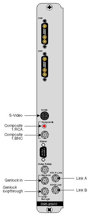
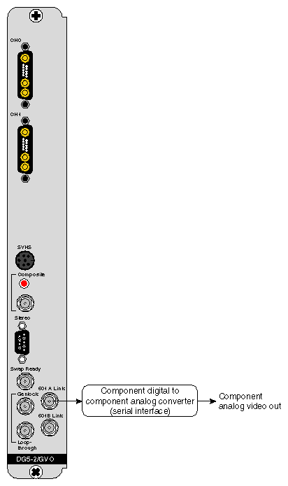
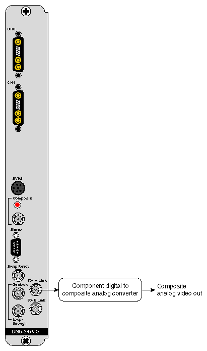
Figure 1-2 shows connectors on the DG5-2/GVO I/O panel. This panel has the connectors for the DG5-2 board and its daughter board, the GVO. The GVO is available only as a daughter board for the DG5-2.
| Note: For brevity, the DG5-2/GVO panel is referred to as the GVO panel in the rest of this chapter. |
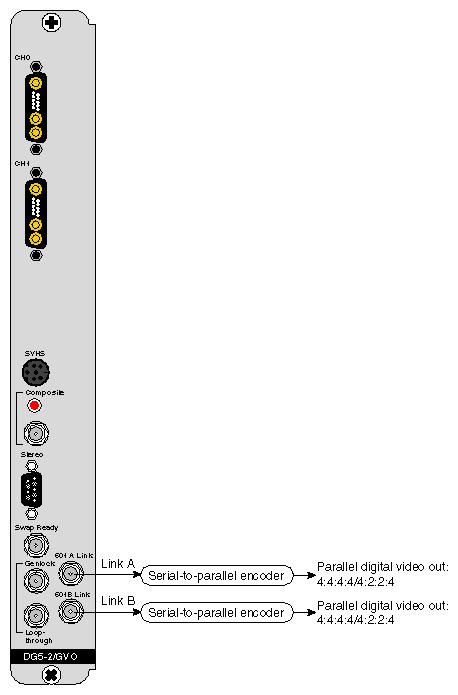
The connectors on the left in Figure 1-2 are actually DG5 connectors; the GVO board itself has only two connectors, labeled 601 A Link and 601 B Link. These are outputs, corresponding to OUT LINK A and OUT LINK B on the DIVO or DIVO-DVC board.
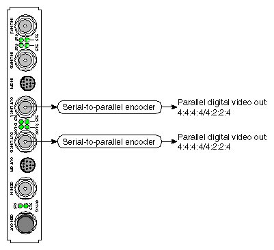
| Note: All DIVO/DIVO-DVC and GVO BNCs are 75-ohm. |
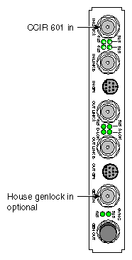
Figure 1-3 shows connection between CCIR 601 (4:2:2, serial digital interface) and DIVO/DIVO-DVC IN LINK A, plus house genlock in. These connections are directly attached cables from the external devices to the DIVO/DIVO-DVC connectors. The genlock connection is optional.
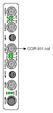
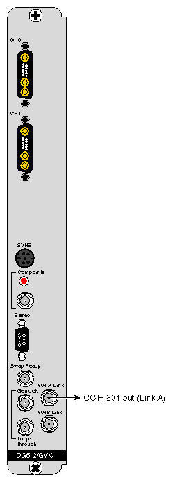
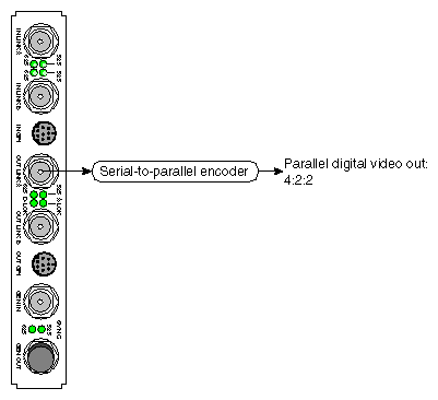
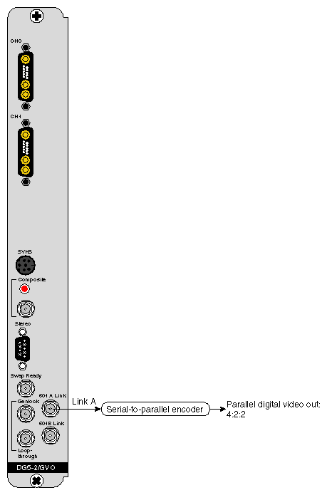
Figure 1-4 shows the connection between DIVO/DIVO-DVC OUT LINK A and CCIR 601; Figure 1-5 shows the connection between GVO OUT LINK A and CCIR 601. This connection is a direct cable between the DIVO/DIVO-DVC or GVO connector and the external video device.
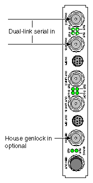
Figure 1-6 shows connections between both DIVO/DIVO-DVC IN BNCs and a dual-link serial digital interface (4:2:2:4/4:4:4:4), plus house genlock. These connections are directly attached cables between the DIVO/DIVO-DVC connectors and the external video devices. The genlock connection is optional.
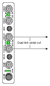
Figure 1-7 shows connections between both DIVO/DIVO-DVC OUT BNCs and a dual-link (4:2:2:4/4:4:4:4) serial digital interface; Figure 1-8 shows connections between both GVO OUT BNCs and a dual-link (4:2:2:4/4:4:4:4) serial digital interface. These connections are directly attached cables between the DIVO/DIVO-DVC or GVO connectors and the external video devices.
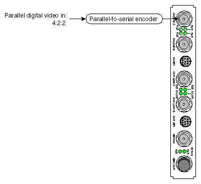
Figure 1-9 shows connections between DIVO/DIVO-DVC IN LINK A and a parallel digital video 4:2:2 (single-link) device.
Table 1-1 summarizes some parallel-to-serial encoders for DIVO/DIVO-DVC IN.
Table 1-1. Parallel-to-Serial Encoders for DIVO/DIVO-DVC IN Connections
Function | Manufacturer | Product | Web Site |
|---|---|---|---|
Encodes parallel digital to serial digital; use two for dual-link | Miranda | SER-100E + power supply or SER-FRA (SER-WSA = 110V power supply) (SER-WSE = 220V power supply) | www.miranda.com |
Rackmount frame with power supply for up to six SER-100E and/or SER-100D | Miranda | SER-FRA | www.miranda.com |
Encodes parallel digital to serial digital; use two for dual-link | Leitch | VPS-7000/7001 | www.leitch.com |
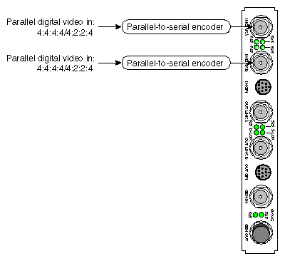
Figure 1-10 shows connections between both DIVO/DIVO-DVC IN BNCs and parallel digital video 4:2:2:4/4:4:4:4 (dual-link) encoders.
Table 1-2 summarizes some parallel-to-serial encoders for DIVO/DIVO-DVC IN.
Table 1-2. Parallel-to-Serial Encoders for DIVO/DIVO-DVC IN Connections
Function | Manufacturer | Product | Web Site |
|---|---|---|---|
Encodes parallel digital to serial digital; use two for dual-link | Miranda | SER-100E + power supply or SER-FRA (SER-WSA = 110V power supply) (SER-WSE = 220V power supply) | www.miranda.com |
Rackmount frame with power supply for up to six SER-100E and/or SER-100D | Miranda | SER-FRA | www.miranda.com |
Encodes parallel digital to serial digital; use two for dual-link | Leitch | VPS-7000/7001 | www.leitch.com |
Figure 1-11 shows connections between DIVO/DIVO-DVC OUT LINK A and parallel digital video single-link devices; Figure 1-12 shows connections between GVO OUT LINK A and parallel digital video single-link devices.
Table 1-3 summarizes some parallel encoders for DIVO/DIVO-DVC or GVO OUT.
Table 1-3. Parallel Encoders for DIVO/DIVO-DVC or GVO OUT Connections
Function | Manufacturer | Product | Web Site |
|---|---|---|---|
Decodes serial into parallel | Miranda | SER-100D + power supply or SER-FRA (SER-WSA = 110V power supply) (SER-WSE = 220V power supply) | www.miranda.com |
Rackmount frame with power supply for up to six SER-100E and/or SER-100D | Miranda | SER-FRA | www.miranda.com |
Decodes serial into parallel | Leitch | VPS-7000/7001 | www.leitch.com/leitch/ |
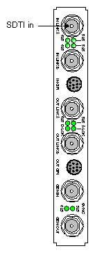
Figure 1-13 shows the connection between the DIVO and DIVO-DVC IN LINK A BNC and a Serial Data Transport Interface (SDTI) device.
You can connect a SMPTE 305M-compliant SDTI deck to IN LINK A to use SDTI on the DIVO or DIVO-DVC option board.
For more information on the SDTI standard, see “Serial Data Transport Interface (SDTI)” in Chapter 1 of the DIVO Option and DIVO-DVC Option Owner's Guide.
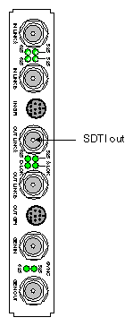
Figure 1-14 shows the connection between the DIVO/DIVO-DVC OUT LINK A and an SDTI device.
You can connect a SMPTE 305M-compliant SDTI deck to OUT LINK A to use SDTI on the DIVO or DIVO-DVC option board.
For more information on the SDTI standard, see “Serial Data Transport Interface (SDTI)” in Chapter 1 of the DIVO Option and DIVO-DVC Option Owner's Guide.
Figure 1-15 shows connections between both DIVO/DIVO-DVC OUT BNCs and parallel digital video 4:2:2:4/4:4:4:4 (dual-link) devices; Figure 1-16 shows connections between both GVO OUT BNCs and parallel digital video 4:2:2:4/4:4:4:4 (dual-link) devices.
Table 1-4 summarizes some parallel encoders for DIVO/DIVO-DVC or GVO OUT.
Table 1-4. Parallel Encoders for DIVO/DIVO-DVC or GVO OUT Connections
Function | Manufacturer | Product | Web Site |
|---|---|---|---|
Decodes serial into parallel; use two for dual-link | Miranda | SER-100D + power supply or SER-FRA (SER-WSA = 110V power supply) (SER-WSE = 220V power supply) | www.miranda.com |
Rackmount frame with power supply for up to six SER-100E and/or SER-100D | Miranda | SER-FRA | www.miranda.com |
Decodes serial into parallel | Leitch | VPS-7000/7001 | www.leitch.com/leitch/ |
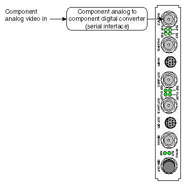
Figure 1-17 shows a connection between DIVO/DIVO-DVC IN LINK A and component analog to serial digital (such as Betacam).
Table 1-5 summarizes some suppliers of component analog converters for DIVO/DIVO-DVC IN.
Table 1-5. Component Analog Converters for DIVO/DIVO-DVC IN Connections
Function | Manufacturer | Product | Web Site |
|---|---|---|---|
Component analog to serial digital | Leitch | 3501AD/CDC3501 | www.leitch.com |
Component analog to serial digital | Nova | ASD-1 | www.nova-sys.com |
Component analog to serial digital | Miranda | ASD-100 | www.miranda.com |
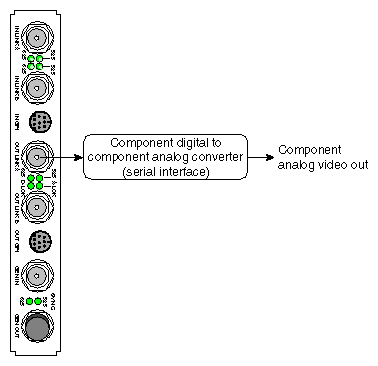
Figure 1-18 shows a connection between DIVO/DIVO-DVC OUT LINK A and component analog (such as Betacam); Figure 1-19 shows a connection between GVO OUT LINK A and component analog.
Table 1-6 summarizes some suppliers of component analog converters for DIVO/DIVO-DVC or GVO OUT.
Table 1-6. Component Analog Converters for DIVO/DIVO-DVC OUT or GVO OUT Connections
Function | Manufacturer | Product | Web Site |
|---|---|---|---|
Serial digital to component analog | Leitch | 3501DA/CDC3501 | www.leitch.com |
Serial digital to component analog | Nova | SDA-1 | www.nova-sys.com |
Serial digital to analog video | Miranda | SDM-110 | www.miranda.com |
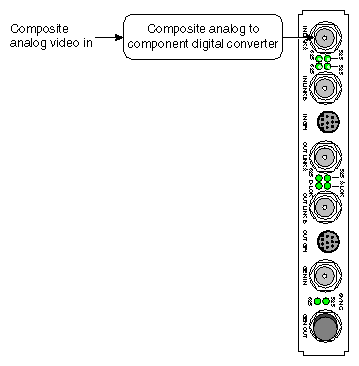
Figure 1-20 shows a connection between DIVO/DIVO-DVC IN LINK A and composite analog (NTSC/PAL).
Table 1-7 summarizes possible suppliers of this equipment.
Table 1-7. Composite Analog (NTSC/PAL) to DIVO/DIVO-DVC
Function | Manufacturer | Product | Web Site |
|---|---|---|---|
Composite analog to serial digital | Leitch | DEC-3610N-AS | www.leitch.com |
Composite analog to serial digital | Accom | C-Bridge DEC | www.accom.com |
Composite analog to serial digital | Nova | ASD-2 | www.nova-sys.com |
Composite analog to serial digital | Miranda | ASD-201i | www.miranda.com |
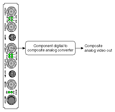
Figure 1-21 shows a connection between DIVO/DIVO-DVC OUT LINK A and composite analog (NTSC/PAL); Figure 1-22 shows a connection between GVO OUT LINK A and composite analog (NTSC/PAL).
Table 1-8 summarizes possible suppliers of this equipment.
Table 1-8. Composite Analog (NTSC/PAL) to DIVO/DIVO-DVC or GVO OUT
Function | Manufacturer | Product | Web Site |
|---|---|---|---|
Serial digital to composite analog | Leitch | CES-3501 | www.leitch.com |
Serial digital to composite analog | Nova | SDA-2 | www.nova-sys.com |
Serial digital to composite analog | Miranda | SDM-201i | www.miranda.com |
Serial digital to composite analog or D2 | Accom | D-Bridge 122 | www.accom.com |
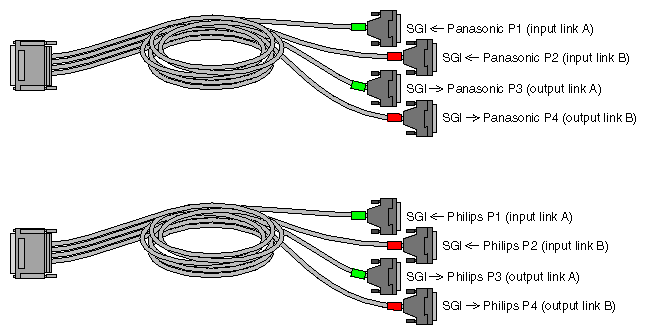
Figure 1-23 shows the two multiheaded cables included with the board; each has four 50-pin connectors for link A input, link B input, link A output, and link B output. The 50-pin connectors differ for each type of cable, following the Panasonic and Philips 50-pin video equipment interface standard.
See “HD I/O Panel and Cable” in Chapter 1 of the HD I/O Option Board Owner's Guide for more information on the cables included with the option.
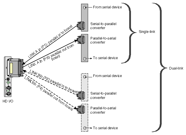
Figure 1-24 diagrams example connections between serializers and the HD I/O board.
Table 1-9 summarizes possible suppliers of this equipment.
Table 1-9. Serializers and Converters for HD I/O Option
Conversion | Product | Manufactur er | Web Site |
|---|---|---|---|
Serial to parallel | SPC-292M AJ-HSP500 | YEM Panasonic | http://www.yem.co.jp http://www.panasonic.co/broadcast, |
Parallel to serial | PSC-292M AJ-SDA500 | YEM Panasonic | http://www.yem.co.jp http://www.panasonic.com/broadcast, |
Combination serial to parallel, parallel to serial | PSP-292M | YEM | http://www.yem.co.jp |
Analog to digital | ADC-292M | YEM | http://www.yem.co.jp |
Digital to analog | AJ-HDA500 DAC-292M | Panasonic YEM | http://www.panasonic.com/broadcast, http://www.yem.co.jp |
Table 1-10 summarizes contact information for video equipment manufacturers listed in this chapter.
Table 1-10. Video Equipment Manufacturer Contact Information
Category | Information |
|---|---|
Manufacturer | Accom, Inc. |
Manufacturer
Address | Leitch Incorporated |
Manufacturer | Miranda Technologies, Inc. |
Manufacturer | Nova Systems |
Manufacturer | Panasonic Broadcast and Digital Systems Co. |
Manufacturer | YEM America Inc. |

