The DIVO and DIVO-DVC boards support four native color spaces—RGB, YUV, CCIR, and RP-175 compressed RGB. The choice of color space is determined by the format control for video sources and drains and by the color-space controls for memory sources and drains. If the color space selected for memory sources and drains matches that used by the current video format, no color-space conversions are performed. When DIVO/DIVO-DVC performs color-space conversions, extreme care is taken to assure the correctness and precision of the result.
Understanding the capabilities of DIVO/DIVO-DVC to perform color space conversions and the results of these conversions allows developers and end users to maximize the quality of their output. This appendix explains
The appendix concludes with examples.
The DIVO/DIVO-DVC option uses a minimum of ten bits of precision for each color component at all steps of its internal pipeline. Representations for the four native internal color representations are explained separately in this section.
RGB is the color space used by the graphics subsystem. RGB has the most accurate representation of visible colors, because all possible combinations are valid. This color space does not support superblack or other nonvisible color values. Each component is represented by a 10-bit value between 0 and 1023. Black has the value [0,0,0], and white is [1023,1023,1023]. Table D-1 summarizes the clamping range for each resulting RGB component for various conversions.
Table D-1. Clamping Ranges for RGB Component Conversions
When converting to... | Each resulting RGB component is clamped to the range |
|---|---|
10-bit RGB | [0..1023] |
8-bit RGB | [0..255] |
12-bit signed RGB | [-2048..2047] |
13-bit signed RGB | [-4096..4095] |
DIVO/DIVO-DVC uses this color space only at the memory interface.
| Note: You should not normally use 4:2:2 coding with RGB data. |
The YUV color space is obtained from RGB by the matrix transformation in the following equation.
 |
The V, Y, and U values range from [0..1023]. Black has the VYU value [512,0,512]. White has the value [512,1023,512].
DIVO/DIVO-DVC uses this color space only at the memory interface. With proper filtering, 4:2:2 coding can be used.
The CCIR color space is obtained from RGB by the matrix transformation in the follwing equation.
 |
The Cr, Y, and Cb 10-bit values are clamped to the range [4..1019]. Black has the CrYCb value [512,64,512]. White has the value [512,940,512]. For 8 bits, the values are clamped to the range [1..254]; black has the CrYCb value [128,16,128], and white has the value [128,235,128].
This color space is used by the component digital formats. The memory interface can use this color space. With proper filtering, 4:2:2 coding can be used.
The RP-175 color space is obtained from RGB by the matrix transformation in the following equation.
 |
When converting to 10-bit R`G`B`, the R`, G`, and B` values are clamped to the range [0..1023]. Black has the R`G`B` value [64,64,64]. White has the value [940,940,940]. Other clamping ranges are the same as the standard RGB case.
This color space is used by the component digital RGB format. The memory interface can use this color space. You should not use 4:2:2 coding with this color space.
DIVO/DIVO-DVC can process and store each color space explained in the previous section. For best precision, the input color space should be maintained through the processing path. For example, an application that implements DDR functionality could choose to store data in the native representation of the input signal: Data from a D1 deck should be stored as a 8-bit 4:2:2 in the CCIR color space. Data from a dual-link telecine could be stored as 4:4:4 10-bit RP-175 RGB. If the application works in this way, no conversions are performed and the data is passed directly through the system. In particular, CCIR601 data coming from a D1 deck is bit-accurate in this case.
However, it might not be desirable for the application to work this way. If that is the case, the application can use all of the conversion, decimation and interpolation capabilities of the DIVO/DIVO-DVC option to perform real-time color space and 4:2:2 ⇔ 4:4:4 conversions.
Conversions are performed only when absolutely required. Each incoming or outgoing stream can be converted from its current color space to any other color space.
The two major concerns when performing conversions from one color space to another are precision and range.
The DIVO/DIVO-DVC board stores colors with a minimum of 10 bits of precision at all steps in its pipeline. When performing color space conversions, the data is converted to 13-bit signed values before being passed to the matrix multipliers. The matrix multipliers have 13-bit coefficients and 26-bit accumulators. The most significant 14 bits of the matrix-multiplication result are passed on to additional hardware, which applies any needed offsets and then clamps to the proper range.
SGI, has verified both through simulation and hardware testing that the maximal error for two conversions (RGB to CCIR to RGB) is two units out of 1024. The matrix coefficients have been biased to round slightly high rather than slightly low to avoid the type of problems that can otherwise easily occur in the blue component.
Different color spaces allocate the available bits of precision in different ways. The RGB space is designed to maximize the accuracy of color representations. The YUV and CCIR color spaces are designed to strongly decouple chrominance and luminance information.
Since RGB represents visible colors, it is contained inside the YUV and CCIR spaces. The CCIR and RP-175 color spaces also have a slight amount of additional headroom that was intended to prevent aliasing artifacts when Finite Impulse Response filtering operations are performed on the digital data.
Any time a conversion operation is performed between CCIR and one of the other color spaces, the colors that are not representable in the destination color space must be somehow mapped into colors that are representable. The usual way to do this is to clamp each component to the available range in the destination color space. Other methods, such as projecting towards the center of the representable space, might produce results that appear to be better in some cases, but imply modification of the original signal and generally result in a loss of saturation.
During conversion from CCIR to YUV, the axes of the two spaces are parallel, so the result of this clamping operation is very predictable. Superblack and superwhite are clipped to black and white, respectively, and oversaturated colors might also be clipped.
During conversion from RGB to YUV or CCIR, clamping never occurs, because all RGB colors are representable in those color spaces.
During conversion from CCIR or YUV to RGB or RP-175 RGB, the results of clamping are much less intuitive, because these conversions involve rotation and scaling operations, with the result that the component axes in one color space don't align with those in the other.
DIVO/DIVO-DVC also supports signed RGB representations with 12 or 13 significant bits. If one of these representations is used, the entire CCIR color space is representable and no clamping will occur. Application software must specifically select this mode and handle the (12/13)-bit data to gain this benefit.
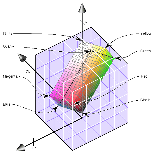
Figure D-1 shows the RGB color cube inside the CCIR color space. The volume contained within the outer (CCIR) cube, but outside the inner (RGB) cube, represents “illegal” colors that cannot be displayed.
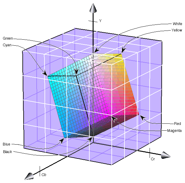
As shown in the figure, the CCIR color space allocates almost three quarters of its available bit combinations to illegal colors. When any of these color values are converted to RGB, the result is clamped to the edge of the RGB cube. Since the inner cube contains the displayable colors, this clamping operation has no impact on them.
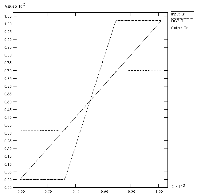
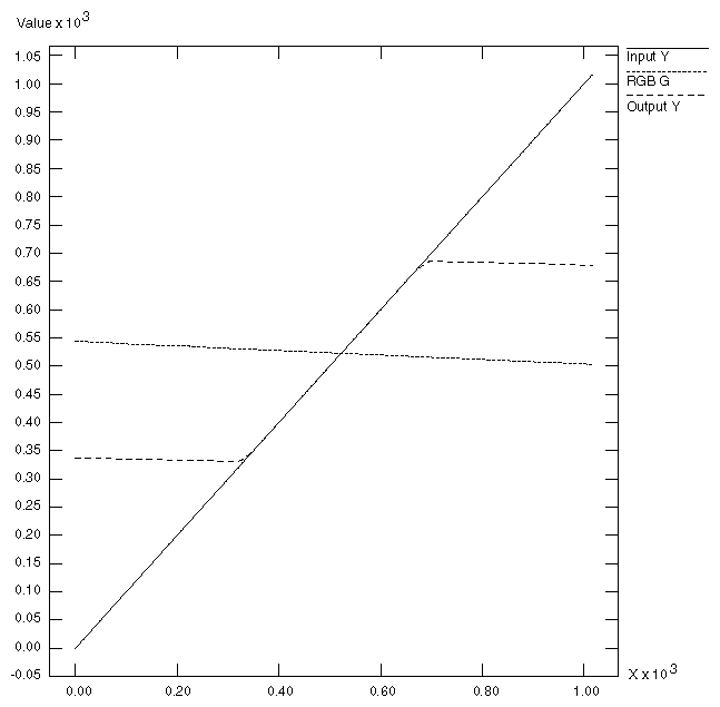
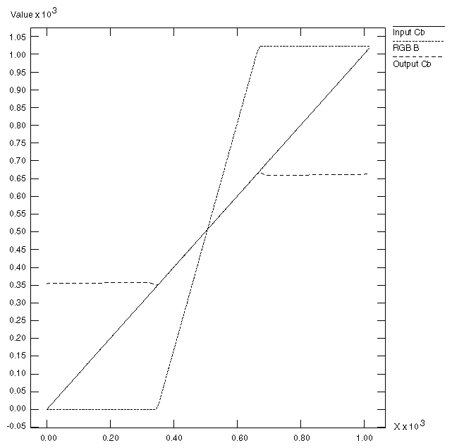
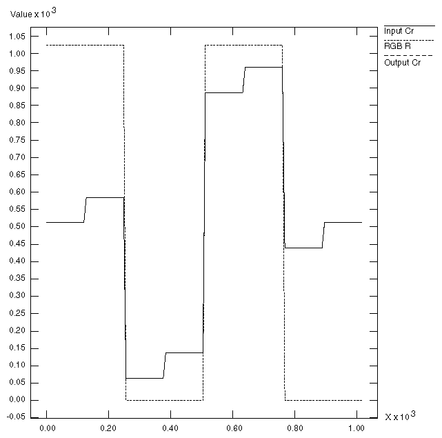
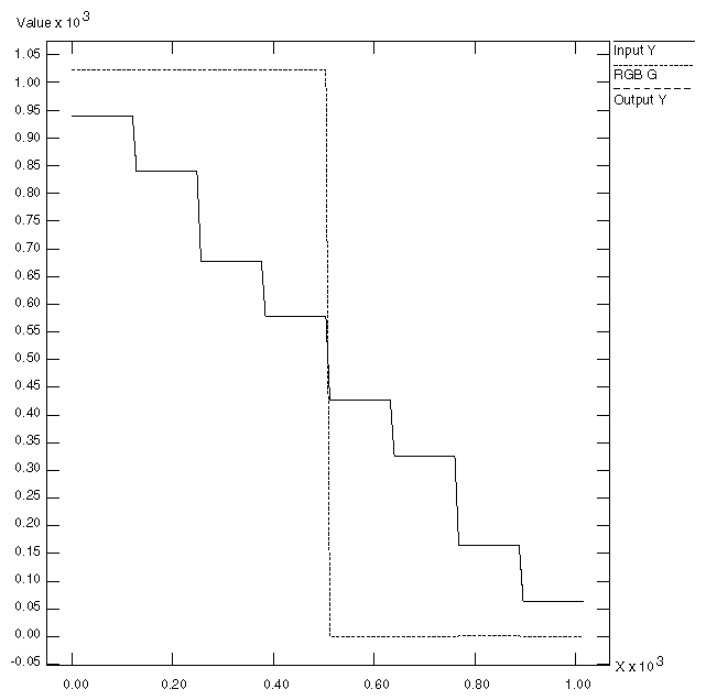
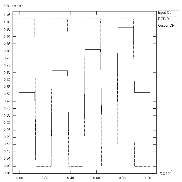
If CCIR is converted to RGB and back to CCIR using certain types of test signals, the output can appear to be vastly wrong. A common and extreme version of this is the signal that simultaneously ramps Cr, Y, and Cb from the minimum to maximum possible values.
In Figure D-2, the heavy diagonal line passing through the figure is the set of colors in the luma/chroma ramp test signal. As shown in the figure, a large portion of this pattern is outside the RGB cube. In fact, over two thirds of this pattern is outside the displayable range.
This section includes example graphs that display the results of converting from CCIR to eight or ten bit RGB and back. They show the same type of result you would see if you passed a digital signal through DIVO/DIVO-DVC using the soft_ee program with RGB as the color space and an eight or ten-bit data-packing. If you use CCIR as the memory color space or use a data-packing with 12/13-bit signed representations, the output will look exactly like the input. If the memory color space matches the video color space, the output will be a bit-perfect copy of the input.
This example, like the other two in this section, consists of three graphs. Each graph displays the input CCIR pattern, intermediate RGB pattern, and output CCIR pattern for a given color component. Figure D-3 shows the red and Cr components, Figure D-4 the green and Y components, and Figure D-5 the blue and Cb components. In this example and the others, if the input and output CCIR values are identical, only two lines are shown.
In this example, conversion to RGB and back has no effect on the image. The 100% amplitude color bar signal lies within the visible range and therefore is perfectly represented in RGB.
In this example, the conversion to RGB and back affects only the superblack and superwhite regions. All luminance values that are blacker than black are clamped to black; all values whiter than white are clamped to white.
In the RGB color space, each component ramps from 0 to 1023 as the input luminance ramps from 64 (black) to 940 (white). This test pattern lies along the Y axis of the color cubes.
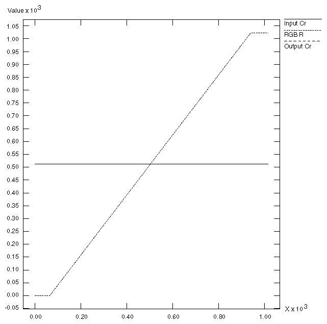
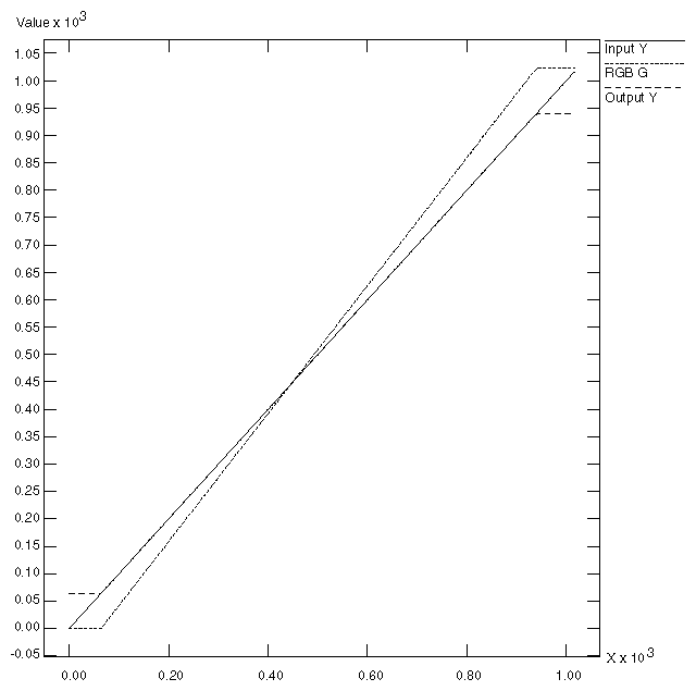
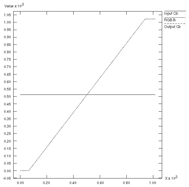
This example is the most extreme of the three, and shows how surprising the results of color conversions can be when arbitrary synthetic CCIR inputs are used.
Each CCIR input signal ramps from 0 to 1023 simultaneously. As mentioned in the first example, over two thirds of this pattern lies outside the legal range. The portion within the legal range is represented exactly, but the region outside is clamped to the RGB cube surface.