This chapter is intended to familiarize you with the physical, electrical, and mechanical aspects of the SGI 2100 server. Standard controls and connectors are described and illustrated along with major components that go in the SGI 2100 chassis. All boards, drives, and other components are housed in a single, upright enclosure and, with its small physical dimensions and quiet operation, the server fits into a lab, server room, or a normal office environment.
Commonly used optional components are also shown and discussed in this chapter.
The SGI 2100 system is a compact, high-performance server that easily fits in most office environments.
The unit weighs a minimum of 120 pounds. (54.5 kg) but is easily moved about on its four rollers. When fully loaded the system could weigh as much as 170 pounds. (77.3 kg). Never attempt to lift the unit without the assistance of other people.
Table 2-1 provides the basic physical specifications for the SGI 2100 system.
See the Site Preparation for Origin Family and Onyx2 manual (P/N 007-3452-nnn) for additional information.
Table 2-1. SGI 2100 System Physical Specifications
Figure 2-1 shows the SGI 2100 chassis and some of its major components.
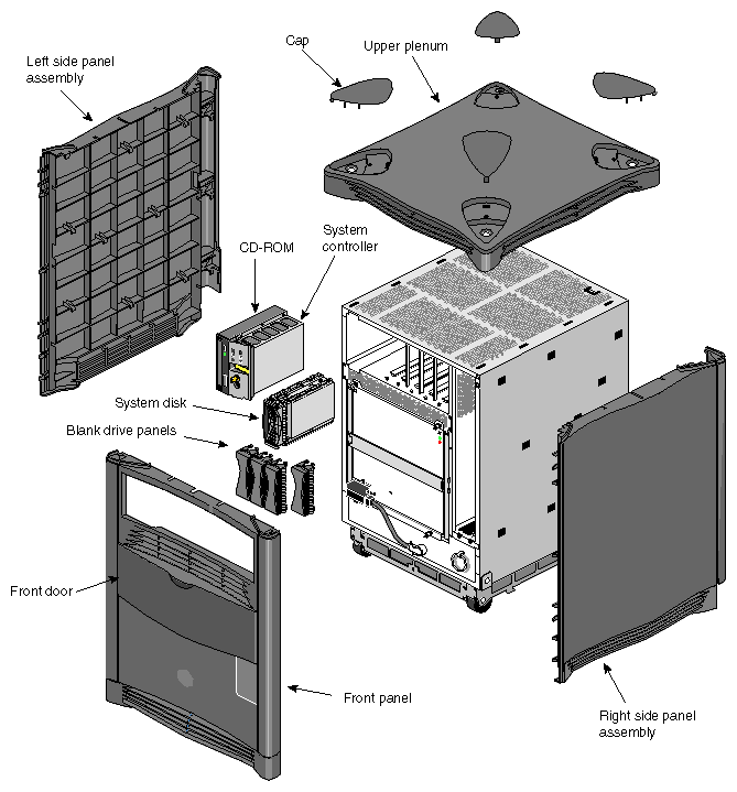
The front of the SGI 2100 system has a number of controls and components that you should be familiar with. The system's removable media drive bay, Module System Controller (MSC), and hard disk drive bays are all accessible by opening the sliding front plastic cover (door).
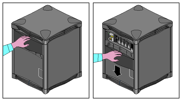
Open the front sliding door panel by pushing it down until it catches (see Figure 2-2).
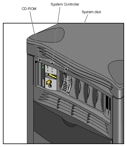
The removable media bay and MSC front panel are next to each other in the upper left corner of the system. Figure 2-3 shows the location of each of these units.
The MSC is located between the disk drive bays and the CD-ROM drive bay. The MSC is a microprocessor-controlled subsystem that is mounted directly to the system midplane by way of an “extender” board. It monitors various system operations, including ambient temperature, system fan speed, midplane voltage levels, and the system clock.
When any operating parameter exceeds or drops past a specified limit, the executes a controlled MSC shutdown of the system. During such a shutdown procedure, the controller maintains a log with the last error message(s) received before the shutdown.
For information on using the MSC, see Chapter 6 in this guide.
The rear of the system houses the following components:
The system node board(s). See Figure 2-5.
The BaseIO system interface panel.
Slots and carriers for optional PCI and XIO interface boards.
The system's main power connector is located on the lower left side of the chassis. The main system power switch is located opposite it on the lower right side.
System power is on when the switch is up and off when it is down.
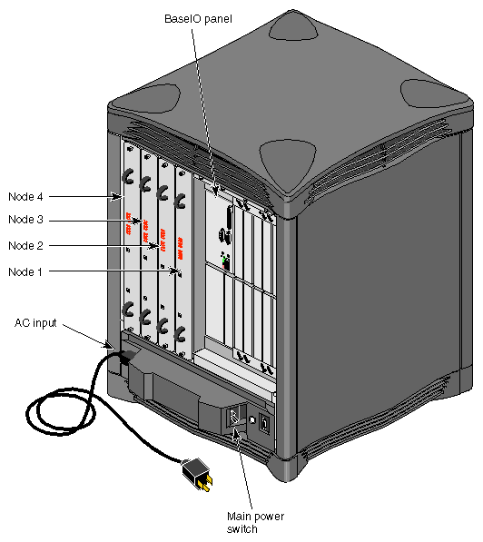
The system node board slots are located in the left side on the rear of the chassis. The first node board is always installed in the right-hand slot. See “System Configuration Guidelines” for information on how the node boards are used in conjunction with other system components.
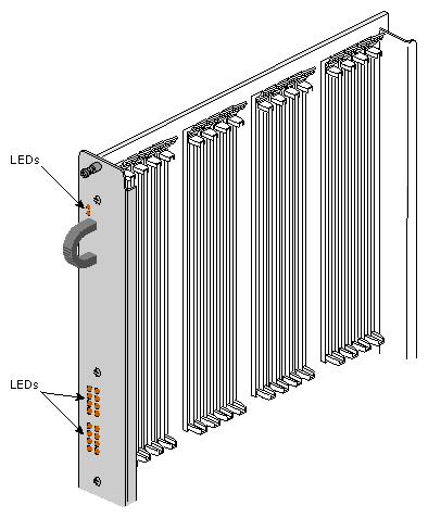
On the back of each node board are a total of 18 LEDs (see Figure 2-6 for an example). Two red LEDs are located near the top of the board and a set of 16 yellow ones are located near the middle of the board.
The two LEDs near the top of the board should light only when there is a voltage inconsistency or problem on the node board. If these LEDs light up frequently, the board may need service. If all the top LEDs on all the node boards in the system light up, it indicates a system-wide power problem. In this case, call your service representative for assistance.
The LEDs grouped near the middle of the board are divided into two vertical sets of eight LEDs (16 total). Each vertical set of eight LEDs represents one of the microprocessors installed on the node board. When only one CPU is installed, you can expect to see LED activity on only one vertical set of LEDs.
As a general rule, the bottom LED should always show some activity while the system is powered on. The bottom LED serves as a kind of “heartbeat” that indicates the CPU is alive, even if the system is not generally active.
The other seven LEDs light up as the number of processes on the CPU increases. The more work the CPU is doing, the more LED activity you see on the back of the node board.
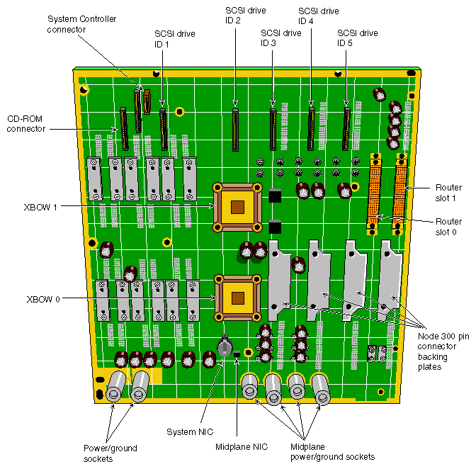
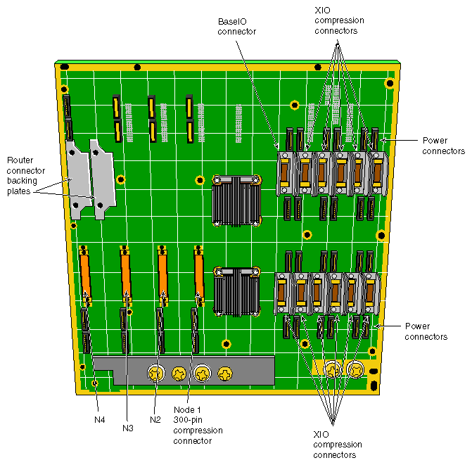
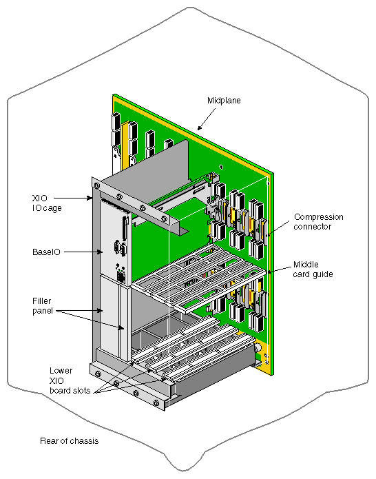
The SGI 2100 enclosure uses a midplane to which boards, disk drives, and other devices can attach from both sides of the system. This allows for maximum functionality and expansion in a compact unit. Figure 2-7 shows a front view of the midplane, while Figure 2-8 shows a rear view.
Single-ended ultra SCSI and SCSI-2 drives are the only devices internally supported by the SGI 2100 system.
The SGI 2100 system is designed to expand in functionality depending on your hardware computing needs. Standard and optional boards can be combined to build a maximum functional configuration.
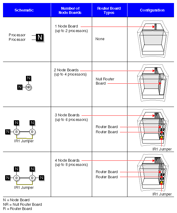
The node and router boards are interdependent and enable high-speed communications within the system among other duties. All SGI 2100 systems ship with the first router board installed. Your system can operate without any router boards, but you can use only one node board and one bank of XIO slots. The first row of configuration information in Table 2-2 shows the restrictions. You must have at least one router board to operate two node boards. Figure 2-9 illustrates the node board and router configuration interdependence.
Table 2-2 provides an overview of interdependent system boards that combine to build the chassis into a maximum compute server.
Node board slots are counted from right to left. Router board and XIO board slots are counted from left to right. Figure 2-10 shows a functional view of the back of the system. The circles ({O}) and triangles (Δ) represent the interdependence of the XIO slots and the node boards that support them.
Table 2-2. Functional Configuration Overview
1st Router Board | 2nd Router Board | 1st and 2nd Node Bd. Slots | 3rd and 4th Node Bd. Slots | XIO Slots 1-6 | XIO Slots 7-12 |
|---|---|---|---|---|---|
Not | Not installed | 1st node {O} is operational | Not usable | Operational{O} | (Δ) Not usable |
Installed | Not installed | 2nd node (Δ) Operational if installed | Not usable | Operational{O} | (Δ) Operational with use of 2nd node board |
Installed | Installed | Operational | Operational | Operational(O) | (Δ) Operational if node 2 installed |
Each SGI 2100 system comes with 12 XIO board slots. Various types of optional interface boards are supported in the XIO slots. These may include
peripheral component interface (PCI)
high-performance parallel interface (HIPPI)
Fibre Channel
graphics interface (SI Viz Console Board)
There are certain installation restrictions that must be followed when XIO boards are installed or removed. Failure to follow these configuration rules may result in system or peripheral malfunction.
Always
Keep the BaseIO (IO6S) board installed in XIO slot 1.
Fill the top XIO slots first (XIO slots 3 and 5 should be filled first).
Have the PCI module installed in XIO slot 2.
Never
Move the BaseIO (IO6S or IO6G) board to a slot other than XIO slot 1.
Have a SCSI board installed in XIO slot 2.
Have an XIO board installed in an unsupported slot (see Figure 2-10).
The main system I/O panel is the BaseIO (also known as the IO6). It is used to connect external devices to the system. The BaseIO panel configuration for SGI 2100 systems is shown in Figure 2-12.
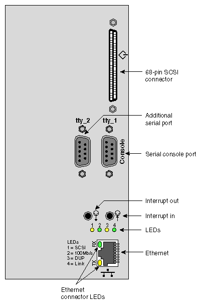
Devices supported by the BaseIO include an Ethernet network connection, ASCII terminals, printers, or modems, and single-ended ultra SCSI or SCSI-2 peripherals.
| Note: If you disconnect a cable from a peripheral device, you should also disconnect it from the I/O connector on the I/O panel. This helps prevent the system from picking up external electrical noise. |
Table 2-3 lists a description of the connectors on the BaseIO.
Connector Type | Connector Description | Connector Function |
|---|---|---|
100BaseT | 8-pin Jack | 100-Mb per second Ethernet |
Serial | 9-pin DIN | RS-232 and 422 Serial |
SCSI | 68-pin (FAST-20) | Ultra SCSI (Single-ended) |
See Chapter 4 in this document for a complete description and pin identification for each of the standard and optional BaseIO connectors.