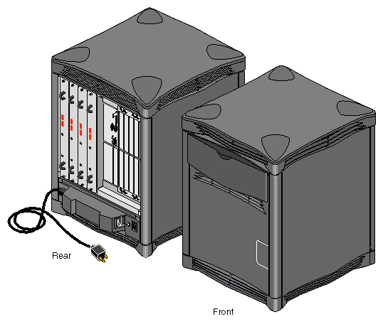
The Origin2000 deskside system, model CMN A015, is a scalable, high-performance server in a compact deskside enclosure. This guide contains end-user hardware information about the deskside system.
The Origin2000 deskside server comes with one to four combined CPU and memory boards called “Node boards.” Each Node board uses one or two R10000™ 64-bit CPU microprocessors. The basic Origin2000 uses one R10000 and the system can use up to eight R10000s when fully configured.
The following standard features come with every Origin2000 deskside server:
One (CPU and memory) Node board with one or two R10000 microprocessors.
Slots for up to 12 optional XIO™ boards. Note that the Origin2000 deskside server does not come with any VME™ slots.
An independent system status monitor (System Controller) that records error information during any unplanned shutdown.
Spaces for up to five half-height single-connector assembly (SCA) SCSI disk drives, plus a 5.25-inch internal drive bay that supports a CD-ROM drive.
A minimum of 64 MB of RAM on each system Node board installed.
additional hard disk drives
a system console ASCII terminal
memory upgrades
XIO boards providing additional I/O, mass storage connections, and graphics capabilities
a three-board optional peripheral component interconnect (PCI) internal adaptor that connects to the XIO slot directly below the BaseIO board (each of the three PCI slots in the adaptor supports a 25 watt PCI board)
The Origin2000 deskside server is similar in size to previous Silicon Graphics deskside systems. However, all of its external and internal features are completely different in design.
The Origin2000 deskside server is a new concept in symmetric multiprocessing systems that uses distributed shared-memory architecture called S2MP™ Architecture. This is a revolutionary (rather than evolutionary) technology step for Silicon Graphics servers.
The Node boards within the Origin2000 use links that differ from bus technology. While a bus is a resource that can be used only by one processor at a time, the communications “fabric” in the Origin2000 makes connections from processor to processor as they are needed. Each Node board contains either one or two processors, a portion of main memory, a directory to maintain cache coherence, and two interfaces:
The first interface connects to multiple I/O devices.
The second interface connects to other Node boards through the S2MP interconnect.
This web of connections differs from a bus in the same way that multiple dimensions differ from a single dimension. You could describe a bus as a one-dimensional line while the Origin2000 uses a multi-dimensional mesh.
The multiple data paths used are constructed as they are needed by router ASICs, which act as switches. As you add Node boards, you add to and scale the system bandwidth.
Main memory on each Node board in the system can be distributed and shared amongst the system microprocessors. This shared memory is accessible to all processors (R10000s) through the S2MP interconnection fabric and can be accessed with low latency.
Each Node board added to the deskside system is another independent memory source, and each Node board is capable of optionally supporting up to 4 GB of memory. A directory memory keeps track of information necessary for hardware coherency and protection.
Each Node board uses a “Hub” ASIC that is the distributed shared-memory controller. It is responsible for providing all of the processors and I/O devices with transparent access to all of distributed memory in a cache-coherent manner. Cache coherence is the ability to keep data consistent throughout a system. In the Origin2000 system, data can be copied and shared amongst all the processors and their caches. Moving data into a cache may cause the cached copy to become inconsistent with the same data stored elsewhere. The Origin2000 cache coherence protocol is designed to keep data consistent and to disperse the most-recent version of data to wherever it is being used.
Although memory is physically dispersed across the system Node boards, special page migration hardware moves data into memory closer to a processor that frequently uses it. This page migration scheme reduces memory latency — the time it takes to retrieve data from memory. Although main memory is distributed, it is universally accessible and shared between all the processors in the system. Similarly, I/O devices are distributed among the Nodes, and each device is accessible to every processor in the system.
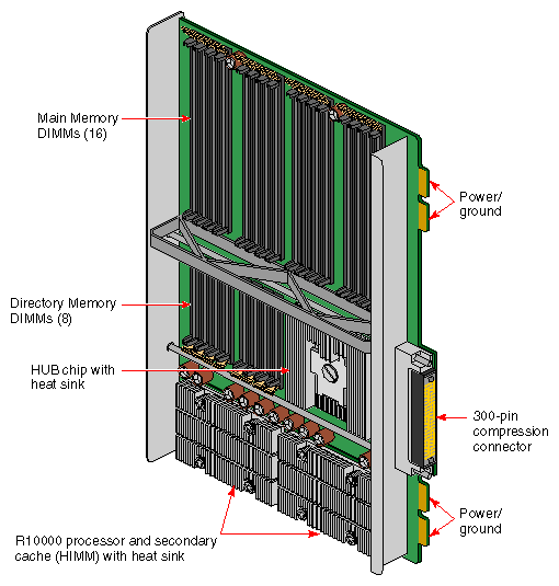
The Origin2000 deskside's microprocessor “brains” and primary memory are located on a processor board called a Node board. Each Node board (up to four maximum) in the Origin2000 deskside can house one or two R10000 microprocessors. Each 3.45-V R10000 uses a customized two-way interleaved data cache, and has dedicated second-level cache support.
A high-performance bus interface links each CPU processor directly with supporting SRAM. The Node board's main memory slots can be populated with 32-MB or 64-MB memory modules. See Figure 1-2 for an example Node board illustration.
Note that directory memory is used only in large-scale rackmounted systems; there is no reason to use directory memory in a deskside system.
The standard I/O subsystem consists of a base I/O board assembly (BaseIO) that supports
two nine-pin serial ports (selectable for RS-232 or RS-422 operation)
a 100-Mb per second (100 Base-T) Ethernet connection
a 68-pin single-ended Ultra SCSI and SCSI-2 compatible connector
Additional I/O connection capabilities are available with optional XIO boards or by ordering an expanded version of the BaseIO.
XIO boards give the Origin2000 deskside system a wide range of optional interfaces in a manner similar to older VME interfaces. Optional XIO boards can support interfaces such as:
PCI
Fibre Channel
HIPPI
Ultra (FAST-20) SCSI and SCSI-2
ATM
Ethernet
Graphics (SI Viz Console Board Set)
Check with your Silicon Graphics sales or support representative for information on these or other optional interfaces available on XIO boards.
The Origin2000 deskside enclosure uses a midplane rather than a backplane like those used in previous Silicon Graphics deskside systems. This means that boards, disk drives, and other devices can plug into both sides of the system.
Located between the disk drive slots and the optional CD-ROM drive bay is the module System Controller (MSC). The MSC is a microprocessor-controlled subsystem that is mounted directly to the system midplane by way of an extender board. It monitors various system operations, including chassis temperature, system fan speed, midplane voltage levels, and the system clock.
When any operating parameter exceeds or drops past a specified limit, the MSC executes a controlled shutdown of the deskside system. For details on using the MSC, see Chapter 6 in this document.
Each Origin2000 comes standard with a system disk installed in drive bay one (next to the MSC). Four additional internal hard drives may be installed.
The CDROM drive is installed directly to the left of the MSCr. Note that single-ended ultra SCSI and SCSI-2 drives are the only internal devices supported by the Origin2000 deskside system.
This section covers the basic requirements for physical location to ensure proper chassis operation.
The deskside chassis is designed to fit into a typical work environment. Take care to maintain the following operating conditions:
The chassis should be kept in a clean, dust-free location to reduce maintenance problems.
The available power should be rated for computer operation.
The chassis should be protected from harsh environments that produce excessive vibration, heat, and similar conditions.
The chassis should ideally have a six-inch (15-cm) minimum air clearance above the top. The first line of Table 1-1 shows the side clearances required if the chassis is positioned under a desk or other equipment and the top air clearance is less than six inches (15 cm). The side air clearances should always be at least as great as those listed on the second line of Table 1-1.
Table 1-1. Air Clearance Requirements for the Deskside System
Top Clearance
Left Side
Right Side
Front
Back
6” (15 cm) or less
6” (15 cm)
6” (25 cm)
8” (20 cm)
8” (20 cm)
More than 6” (15 cm)
1” (2.5 cm)
1” (2.5 cm)
6” (15 cm)
6” (15 cm)
For more information on system specifications, see Table 2-1 in Chapter 2.
If you have additional questions concerning physical location or site preparation, see the Site Preparation for Origin Family and Onyx2 manual (P/N 007-3452-nnn). If you are unable to find the information you need, contact your Silicon Graphics System Support Engineer (SSE) or other authorized support organization representative.

