This appendix consists of example exercises designed to demonstrate tasks you can perform using the video combiner utility with your graphics system. It includes:
modifying video formats
saving video format combinations to the GE board's EEPROM
resizing a single-channel combination
using ircombine with GVO
This appendix also includes instructions for redisplaying graphics if the monitor should stop displaying video during one of the examples (or at any other time).
The information in this appendix is intended only as an introductory overview of the Combiner. For more detailed information on using the Combiner with your Onyx2 graphics system, see the InfiniteReality Video Format Combiner User's Guide.
The example exercises in this appendix are based on the assumption that a Silicon Graphics multisync monitor is connected to Channel 0. If the monitor attached to Channel 0 is unable to sync to any of the formats used in the example, it ceases displaying video.
The first time graphics was initialized, or during the first power-on of the system with graphics installed, the video output was defined for the channels available on the workstation. To reinitialize graphics, enter
(/usr/gfx/stopgfx ; /usr/gfx/startgfx) & |
at the IRIX prompt. Note that the parentheses are necessary.
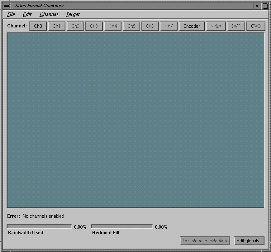
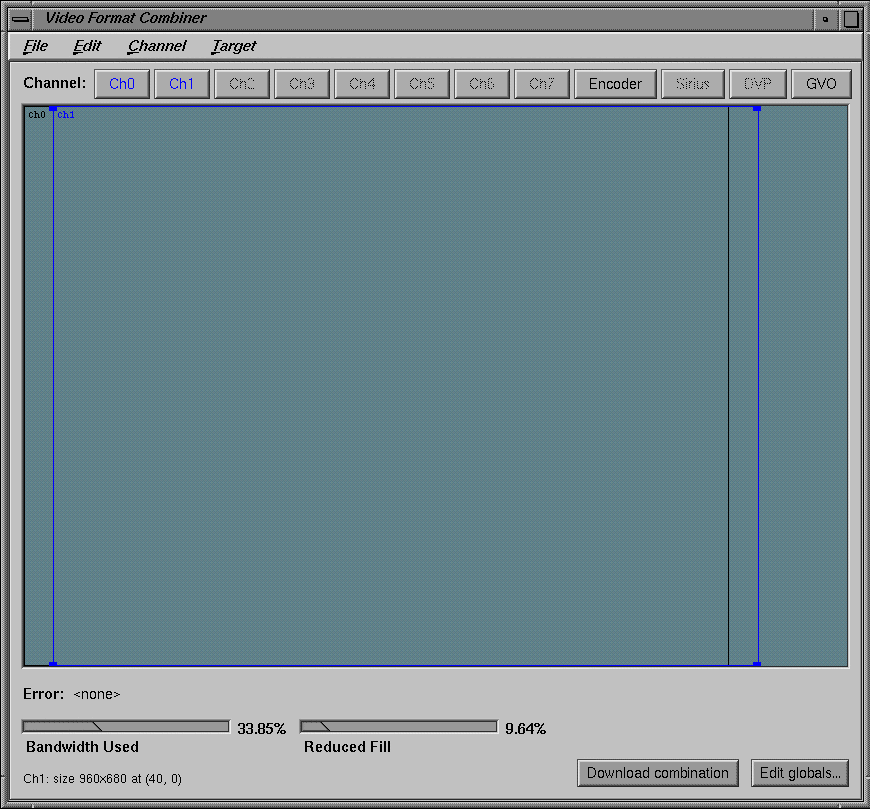
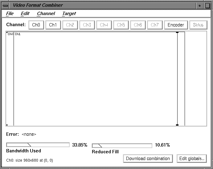
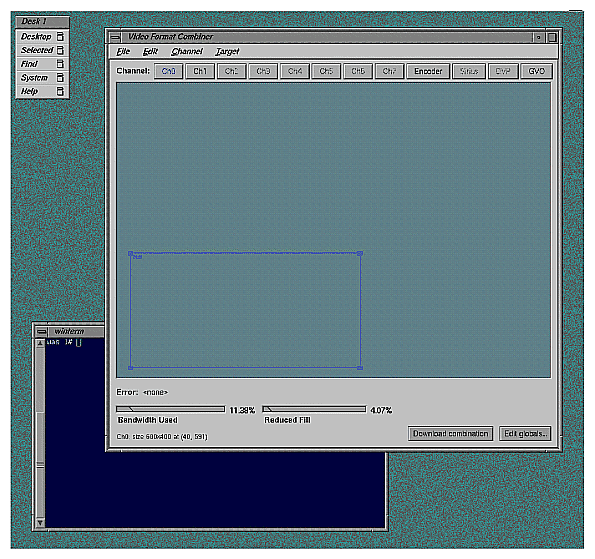
FigureáD-1 shows an example of the main window interface.
Each example starts from the Combiner's main window.
This exercise consists of
performing steps to avoid a reboot
selecting a video format for Channel 0
selecting a video format for Channel 1
Each procedure is explained in a separate section.
Before modifying and downloading new video format combinations, you can avoid having to reboot the graphics system if you select a combination of window sizes that do not encompass the Combiner main window controls or an IRIX shell window. Follow these steps:
Bring up an IRIX shell window and reduce it to 80 x 24 using the size option on the pulldown menu from mouse button three.
Drag the IRIX shell to the lower left corner of the screen.
Launch the Combiner main window (if you have not already done so).
Position the Combiner's main window in the upper left corner of the screen.
Resize the Combiner's main window so that none of the IRIX shell window is covered: click the lower right corner of the Combiner main window and move it upward.
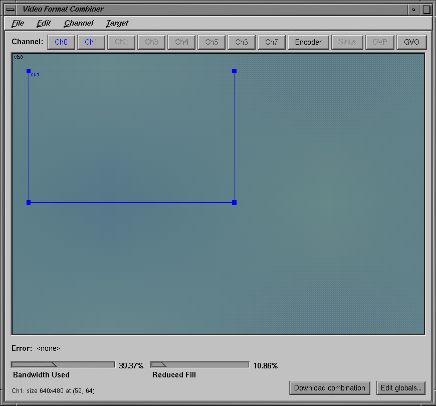
FigureáD-2 shows the main window with Channels 0 and 1 in the managed area.
To select the first channel to modify (Channel 0), follow these steps:
Click Ch0 in the Combiner main window. This selection corresponds to Chan0 connections on the system's I/O panel.
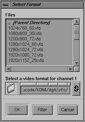
In the Files window that appears, select the 640x480_60.vfo file as the video format for that channel; see FigureáD-3.
Click OK. The Ch0 rectangle appears in the Combiner's main window.
Do not close the Files window.
Click on the bottom line (not the corner) of the rectangle and drag it to the bottom left corner of the main window.
Select and modify Channel 1 using the following steps:
Click Ch1 on the main window.
Move the cursor to the Files window and click the 640x480_60.vfo file option.
Click OK. A Channel 1 (Ch1) rectangle appears in the upper left portion of the Combiner main window.

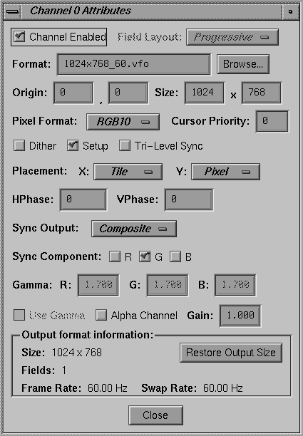
Note: In this example, you set the origin of Channel 1 precisely to (4,10). You could do this by clicking on the line of the rectangle and dragging it, as you did for Channel 0. However, in this exercise you specify the Ch1 origin numerically by editing the Ch1 attributes in the following steps. Bring up the Attributes window by double-clicking the Ch1 button in the Combiner main window. The Channel 1 Attributes window appears, as shown in FigureáD-4.
Click the cursor in the first (far left) Origin box.
Replace the value in the left Origin box (the x-origin box) with 4; press Enter.
Move to the right Origin box (the y-origin box) and replace the value with 10; press Enter. See FigureáD-4 for an example.
Click Close in the Attributes window.
Move the cursor to the Combiner main window and click Download combination.
At this point, the video system is displaying the configuration specified in the exercise just completed:
Channel 0 is displaying the lower left portion of the frame buffer where you originally placed the IRIX shell window.
Channel 1 is displaying the upper left portion of the frame buffer where the Combiner's main window was placed.
To return to a 1280 x 1024 video output, enter /usr/gfx/setmon -n 1280x1024_72 in the IRIX shell window.
Go on to the next example or close the Combiner's main window.
Before starting this exercise, be sure to read the information in “Reinitializing Graphics and Starting Combiner”.
This example assumes that the Combiner main window is open. If it is not, follow the instructions at the beginning of this appendix.
In the Combiner main window, select “New” from the File pulldown menu. Then click OK in the warning box. You are now ready to create and save a new video format combination to the GE board's EEPROM. The video format consists of two channels; each one is a 960x680_60.vfo format. Use the following steps to make and save all the changes:
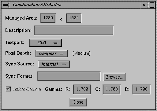
Click Edit globals in the main window's bottom right corner. The Combination Attributes window appears, as shown in FigureáD-5.
Change the Managed Area fields at the top of the Attributes window to read 1000 in the left-hand box and 680 in the right-hand box.
Click the Attributes window's Close button.
Click Ch1 in the Combiner's main window. The Select Format box appears.
Find and double-click the 960x680_60.vfo file format. An error message appears at the lower left corner of the Combiner's main window, as shown in FigureáD-6: “Textport channel Ch0 invalid.”
When this or any other error message appears in the main window, you cannot use the “Download combination” or “Save to EEPROM” functions. In this example, the error condition goes away after you define Ch0.
Click and drag the Channel 1 (Ch1) box on the main window to the right until it is blocked by the red vertical line.
The red line represents the right-hand boundary of the specified Managed Area (1000) that you entered in step 2. The excess space to the right of the red line represents an unusable area. The Combiner does not permit you to position channels in that area.
Click Ch0 in the Combiner main window.
In the Select Formats box that appears, find and double-click the 960x680_60.vfo file format.
At this point, you have specified a video format combination with two video formats that are both equal to 960x680_60. The two channels are slightly offset but mostly overlapping, as shown in FigureáD-7.
In the File pulldown menu in the Combiner's main window, select “Save to EEPROM.“
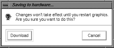
In the “Saving to hardware” dialog box that appears, click Download (see FigureáD-8).
The format combination is now loaded in the GE board's EEPROM, but it does not take effect until the graphics subsystem is restarted.
In the File pulldown menu in the main window, select Exit.
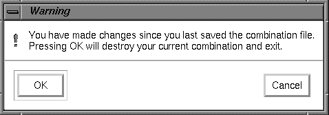
Click OK when the Warning dialog box appears (see FigureáD-9).
Enter the following in the IRIX shell window to restart system graphics:
(/usr/gfx/stopgfx ; /usr/gfx/startgfx) &.
When the Login window appears, log in as root (superuser). The video system is now outputting a 960x680_60 format on Channels 0 and 1.
The video system retains this configuration even after rebooting because the 960x680_60 Video Format Combination is saved in the GE board's EEPROM.
To reset the EEPROM to the standard 1280 x 1024 format combination, enter /usr/gfx/setmon -n 1280x1024_72 at the IRIX prompt. Then restart the graphics system (as in step 13) to activate the format combination reset. When the Login window appears, log in as root.
Before starting this exercise, be sure to read the information in “Reinitializing Graphics and Starting Combiner”.
In this final example, you create a single-channel combination that is “static resized” and is saved to and loaded from a combination file. Follow these steps:
Open an IRIX shell window, click the third mouse button and use the Size pulldown menu to change the shell to 80 x 24.
Place the 80 x 24 shell window behind the Video Format Combiner main window, but make sure the command-line prompt is visible.
Click Ch0 on the Combiner's main window. The Select Format window appears.
Find and double-click the 1280x1024_72.vfo file. The Channel 0 (Ch0) rectangle fills the entire 1280 x 1024 managed area in the main window.
In the Channel pulldown menu, select “Grab Window.” The cursor turns into a cross.
Move the cross (cursor) into the IRIX shell window and click the mouse button. The rectangle in the Combiner's main window representing Ch0 now represents the area of the framebuffer covered by the 80 x 24 IRIX shell that you clicked in. See FigureáD-10 for a screen example.

Note: This area becomes resized to fit the entire Channel 0 output when the combination is loaded. You can resize a channel's input area by clicking and dragging any of the four corners of its main window rectangle. That resizing method is not covered in this exercise. 
Caution: Do not move the IRIX shell window until you complete this exercise.
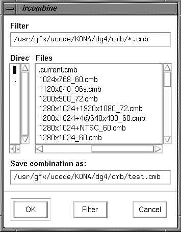
From the File pulldown menu in the Combiner main window, select “Save As.” The ircombine window appears (see FigureáD-11).
In the “Save combination as” field, type test.cmb at the end of the path and click OK.
Select “Exit” from the File pulldown menu in the Combiner's main window.
In the shell window you clicked in step 6, enter
% /usr/gfx/setmon -n test
The screen blanks momentarily and then displays the IRIX shell window resized to 1280 x 1024 (the entire screen display).

Note: If no usable window appears, you can recover the default video display combination following the instructions in “Redisplaying Graphics”. Revert to the previous display configuration by entering
% /usr/gfx/setmon -n 1280x1024_72.
The entire screen should reappear in the 1280 x 1024 format.
Select Exit from the File pulldown menu on the Combiner's main window to conclude the exercise.
The Graphics to Video Option (GVO) provides direct graphics output to broadcast component digital video devices. If you have this option installed in your system, the GVO button on the main panel of ircombine will be enabled, and you will have an additional channel available under ircombine.
To define a combination using GVO in genlocked mode, complete the following steps:
Click CH0 in the combiner window. Select 1280x1024_60.vfo from the files window. Click OK. A large Ch0 rectangle will appear in the combiner window.
Click GVO in the combiner window. A small GVO rectangle will appear in the upper-left corner of the combiner window.
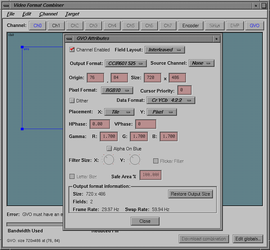
Bring up the Attributes window by double-clicking the GVO button in the Combiner window, or by selecting Edit Attributes from the Channel menu. The GVO attributes window will appear (see FigureáD-12). From this panel you can select a number of options for the GVO output channel. You should pay particular attention to the Output Format, Source Channel, Pixel Format, Data Format and Gamma settings on this panel. When you have selected the values you want, click the Close button.
GVO is normally used with the graphics subsystem genlocked to an external video source connected to the genlock input of the DG5 board. To enable this functionality, complete the following steps:
Click the Edit Globals button on the main combiner window.
Open the Sync Source menu and select External as the value.
Click the Browse button next to the Sync Format text box.
Select 646x486_30i.vfo as the sync format and click OK.
You may now save or download this combination as usual. If you are working in an 50Hz environment, you would use 1280x1024_50.vfo on channel 0 and 768x576_25i.vfo as the external sync format.
If the monitor should stop displaying video during one of the examples or during any other type of Combiner use, the following steps should provide a solution:
Connect a monitor to Channel 0 that can display the required format(s). If video is still not visible, go on to step 2.
Log in to the system remotely or connect an ASCII terminal to serial port tty_1, if possible. Become superuser (root) and enter the command
# /usr/gfx/setmon -n 72
If this does not work, enter
# /usr/gfx/setmon -x 72
Restart the graphics by entering
# (/usr/gfx/stopgfx ; /usr/gfx/startgfx) &.
Reboot the system using the System Controller if the first two steps do not work. If, after rebooting, the video still does not display, wait for several minutes and go to the next step for an additional process.
Enter 1; attempt to reboot the system to single user by entering
# /usr/gfx/setmon -x 72
(even though you are unable to see any screen display of your inputs). When you believe you have succeeded, reboot again.
Call your Onyx2 service provider for additional information and assistance if these steps do not restore your system's video output.
The Combiner interface has many functions besides those listed in the previous examples. You can use the Combiner to
define a channel using an on-screen window as input
copy an existing channel format and content to a new channel
align one channel with another
change the video format for a channel (or delete it entirely)
edit the attributes (size, pixel format, and so on) of a channel
select the “field layout” order in which data is scanned from the framebuffer
select and copy a video format stored in a different file
choose an output pixel format for a particular channel
control cursor behavior in overlapping rectangles by setting the cursor priority
allocate pixel width and depth for framebuffer fields
set horizontal and vertical phase for a given channel
specify whether sync components have sync enabled by default
modify the brightness characteristics of the monitor
change the default output video gain value for a channel
save a combination of all the channels present in the Combiner's main window and make global changes to them
arrange the pixels (set pixel depth) in the framebuffer to optimize framebuffer output speeds
select the internal sync (or use an external source that is connected to the “Genlock In” port)
save a video format combination as a default and write it to EEPROM
run a user-defined hardware configuration simulating more RM/TM boards than you have installed (used when an application is too large).
