This chapter provides background information that helps you successfully set up the disks and disk device files on your system.
The major sections in this chapter are:
If you are installing a disk drive, see the installation instructions furnished with the hardware. Disk administration procedures are described in Chapter 2, “Performing Disk Administration Procedures”. For information on XLV logical volumes and filesystems, begin with Chapter 3, “XLV Logical Volume Concepts”.
| Note: For information on disk layout and disk partitioning with the XVM Volume Manager, see the XVM Volume Manager Administrator's Guide. |
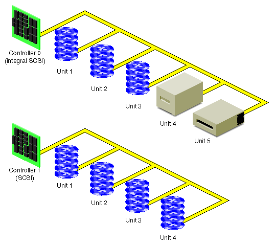
Figure 1-1 shows how disk drives and other peripheral devices are connected to controllers in systems.
Each disk drive is managed by a controller. Each type of controller can support a fixed number of drives. Your workstation can support a fixed number of controllers. (For the number and type of controllers supported by your model of workstation, see your hardware owner's guide.) SCSI controllers support up to seven disks per controller or up to 15 disks per controller (depending upon the SCSI controller type), and VME controllers support up to 14 disks per controller.
Each disk is assigned a drive address (called the unit number in output from the hinv command and also known as a SCSI ID). This address is set by a switch, a dial, or jumpers on the disk, or by the physical location of the disk. See the hardware owner's guide for the system for information on setting the drive address of a disk.
Some SCSI devices, such as RAIDs (an array of disks with built-in redundancy), have an additional identifying number called a logical unit number or lun. It is used to address disks within the device.
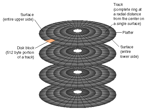
Figure 1-2 shows the physical structure of a disk. A disk consists of circular plates called platters. Each platter has an upper and lower oxide-coated surface. Recording heads, at least one per surface, are mounted on arms that can be moved to various radial distances from the center of the platters. The heads float very close to the surfaces of the platters, never actually touching them, and read and record data as the platters spin around.
As shown in Figure 1-2, a ring on one surface is called a track. Each track is divided into disk blocks. Sometimes called sectors, these physical blocks on a disk are different from filesystem blocks.
Formatting a disk divides the disk into tracks and disk blocks that can be addressed by the disk controller, writes timing marks, and identifies bad areas on the disk (called bad blocks). SCSI disk drives are shipped preformatted. They do not require formatting at any time. Bad block handling is performed automatically by SCSI disks. Bad blocks are areas of a disk that cannot reliably store data. Bad block handling maps bad blocks to substitute blocks that are in a reserved area of disk that is inaccessible by normal IRIX commands.
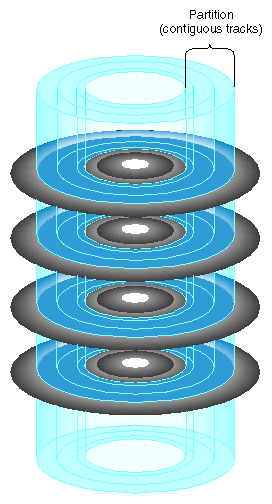
Disks are divided into logical units called partitions. Figure 1-3 shows an example of a partitioned disk. Partitions divide the disk into fixed-size portions that can be used by IRIX or by users for different purposes. Partition sizes are measured in 512-byte disk blocks. On SCSI disks, partitions only need to be integral numbers of disk blocks.
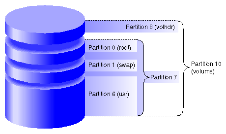
Each disk block can belong to any number of partitions, including no partition (in which case the disk space is unused or wasted). This means that partitions can overlap. For example, a disk can be divided into several non-overlapping partitions and have an additional partition defined that is the entire disk.
Each partition on a disk has a number from 0 through 15. By convention, some of these partition numbers have a particular function and a name. Table 1-1 shows these numbers, names, and functions
Table 1-1. Standard Partition Numbers, Names, and Functions
Partition Number | Name | Function |
|---|---|---|
0 | root | Root partition, used for the root filesystem on system disks. |
1 | swap | Swap partition, used by IRIX for temporary storage when there is less physical memory than all of its processes need. |
6 | usr | usr partition, used on system disks when separate root and usr filesystems are used. |
7 | (none) | The entire disk except the volume header and xfslog partition (if present). |
8 | volhdr | Volume header (see the section “Volume Headers” |
9 | (none) | Reserved partition (historically, this partition was the bad block partition on non-SCSI drives). |
10 | volume | |
15 | xfslog | A small partition used for an XFS log (see “Partition Types” |
System disks contain the IRIX operating system. Specifically, they must contain a volume header that includes sash (see “Volume Headers”),the root filesystem, a swap partition, and possibly a usr filesystem. Each workstation or server has one system disk; IRIX is booted from this disk when the system is brought up. On workstations, the system disk is on controller number 0 and drive address 1 by default. On some servers, the default controller and drive address for the system disk is controller 1 and drive address 1. The location of the system disk is reported by the nvram command; it is the value of OSLoadPartition.
All disks on the system other than the system disk are known as option disks. Disks are shipped from Silicon Graphics with one of several standard partition layouts which are described and illustrated in this section. You can list the partitions of a disk with the prtvtoc command (see the “Displaying a Disk's Partitions With prtvtoc” in Chapter 2).
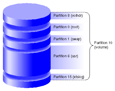
Figure 1-4 and Figure 1-5 show the two common layouts of a system disk with separate partitions for the root and usr filesystems. The layout in Figure 1-4 is used for EFS filesystems and for XFS filesystems when the XFS log does not have its own partition (it is an internal XFS log). Figure 1-5 shows the partition layout when an XFS log partition is included (an external log).
Separate root and usr partitions were standard on older systems and are still used on servers. In the original UNIX design, only the root filesystem needed to be mounted to boot UNIX. This is not true for IRIX anymore—both filesystems must be mounted, so there is no longer the concept of the root filesystem being a minimal subset of operating system software.
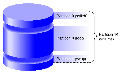
Figure 1-6 shows the layout of a system disk with a single partition for a combined root and usr filesystem and a swap partition. This arrangement is standard on most newer systems. However, restrictions on making the root partition part of an XLV logical volume may make separate root and usr partitions a better choice than a single combined partition (see Chapter 3, “XLV Logical Volume Concepts”, for information about XLV logical volume restrictions).
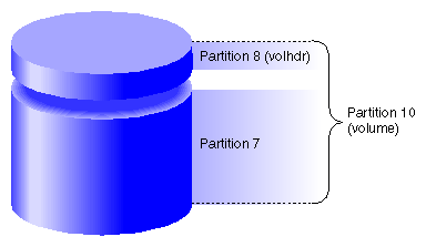
Figure 1-7 shows the standard layout of an option disk that does not have an XFS log partition. It has a single partition for data.
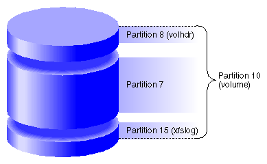
Figure 1-8 shows the layout of an option disk with two partitions, one for data and one for an XFS log.
The default partition layouts are generic in nature and should be evaluated by the system administrator. After your system has been in operation for a few months, you may decide that a different arrangement would better serve your users' needs. Consider the following points in choosing partition layouts:
A single file can not be larger than its filesystem.
When disks are partitioned into several filesystems, a runaway process that writes a file fills just a partition rather than the entire disk.
A large root partition ensures that you can install future, and most likely larger, IRIX system software releases without running out of disk space in the root filesystem.
Use the fx command to change disk partitions (called repartitioning a disk). The command can be used with standard partition layouts or to create custom partition layouts. For additional information on using fx to repartition disks, see “Repartitioning a Disk With fx” in Chapter 2.
Once you partition disks, you can use these partitions as filesystems, as parts of an XLV logical volume, or as raw disk space. XLV logical volumes are described in Chapter 3, “XLV Logical Volume Concepts”. Filesystems are described in Chapter 5, “Filesystem Concepts”.
Each partition has a type that is displayed by fx and prtvtoc. Table 1-2 lists the partition types, their uses, and the partition numbers that can be assigned to those types. (Partition 9 isn't listed in this table; remember that it is reserved.) Partition types, except for xlv, are assigned by fx. The type xlv is automatically assigned by several XLV logical volume commands.
Table 1-2. Partition Types and Uses
Partition Type | Partition Use | Partitions That Can Be This Type |
|---|---|---|
efs | EFS filesystem | 0, 6, 7 (standard partitions); |
xfs | XFS filesystem | 0, 6, 7 (standard partitions); |
xfslog | External log for an XFS filesystem (part of an XLV log subvolume) | 15 (standard partition); |
raw | Swap space | |
volhdr | Volume header | |
volume | Entire volume, including the volume header | |
xlv | Part of an XLV data or real-time subvolume | 0, 1, 2, 3, 4, 5, 6, 7, 11, 12, 13, 14, 15 (partitions are changed to type xlv by XLV commands) |
lvol | Part of an lv logical volume | This partition type is now obsolete. lv logical volumes must be converted to XLV logical volumes. See “Converting lv Logical Volumes to XLV Logical Volumes” in Chapter 4 . |
The partitions listed as standard partitions in Table 1-2 are created when you use the fx repartition functions rootdrive, usrrootdrive, and optiondrive. Prompts ask you whether you want partition type efs or xfs. If you specify xfs for usrrootdrive or optiondrive, prompts ask whether you want an xfslog partition. To use an xfslog partition (an external XFS log), you must configure the xfslog partition as an XLV log subvolume. (See Chapter 4, “Creating and Administering XLV Logical Volumes”, for more information about XLV.) If you do not use an xfslog partition, the XFS log is stored in an xfs partition (and called an internal log).
To assign a partition type to a partition number listed as a custom partition in Table 1-2, you must use the expert mode of fx (fx –x) to create the partition and assign the type. (See the fx(1M) reference page for more information about the expert mode of fx.)
A partition called the volume header is stored on the partition that begins at disk block 0. (For proper system operation, the volume header must begin at disk block 0). It contains a minimal filesystem with a few files that contain information about the device parameters, the partition layout, the version number of the most recently used version of fx, and logical volume information. It also may contain some standalone programs.
The files and standalone programs that may be in a volume header are:
| sgilabel | This file contains fx version number information. It is important not to delete this file from the volume header. | |||||||||
| symmon | symmon is a standalone program used to debug the kernel. See the symmon(1M) reference page for more information. | |||||||||
| xlvlab* | XLV logical volume information is stored in files called logical volume labels in the volume header. XLV logical volume information is stored in files whose names begin with xlvlab. This information is used by the system to assemble XLV logical volumes when the system is booted. XLV logical volume labels are created automatically when XLV logical volumes are created. | |||||||||
| lvlab* | Logical volume labels for lv logical volumes were stored in files whose names began with lvlab. lv logical volumes are no longer supported. | |||||||||
| ide | ide (integrated diagnostics environment) is a diagnostics program for low-end systems only. ide is executed when you choose the third item, “Run Diagnostics,” on the System Maintenance Menu. Newer systems execute ide from the /stand directory if it is not in the volume header. | |||||||||
| fx | fx is the standalone version of the IRIX fx command. It is a disk utility used primarily for repartitioning disks. Older systems sometimes included a copy of the command fx in the volume header. There is no longer any need for fx in the volume header. | |||||||||
| sash | On system disks, a copy of the standalone program sash (the standalone shell) must be in the volume header; it is required to boot a system. sash is a processor-specific program. Therefore, if you ever need to copy it from the /stand directory of another system or from the /stand directory of a software distribution CD, you must copy the correct version. If you copy from another system, both systems must have the same processor type. If you copy it from a software distribution CD, use the hinv command to identify the processor type of your system and Table 1-3 to identify the version of sash needed for that system. Table 1-3. Processor Types and sash Versions
|
The fx command can be used to display and modify the device parameters and the partition layout. See the fx(1M) reference page and the section “Repartitioning a Disk With fx” in Chapter 2. Using fx has the side effect of creating the file sgilabel in the volume header.
The command prtvtoc is also used to display partition layout information. See “Displaying a Disk's Partitions With prtvtoc” in Chapter 2 for instructions.
The dvhtool command can be used to add and delete standalone programs from the volume header. dvhtool can also be used to delete XLV logical volume labels from the volume header. See “Adding Files to the Volume Header With dvhtool” in Chapter 2, and “Removing Files in the Volume Header With dvhtool” in Chapter 2 for more information.
The volume header is consulted (and therefore any mistakes made creating or modifying the volume header become apparent) only at these times:
During the boot up process
When creating or growing filesystems
When creating or growing logical volumes
When adding swap areas
IRIX programs communicate with hardware devices through two types of files, called special files. The two types are character device files (also called raw device files) and block device files. Conceptually, a disk device is treated as if it were a file. In practice, there are differences between regular files and device files, so the latter are referred to as special files.
Drivers that have been written to be hardware graph aware produce real device nodes in /hw which are not modifiable by any user-level command. These have links back into the familiar /dev device nodes to provide the standard pathnames used by most programs and administrators. Disk devices are among these hardware graph aware drivers. Drivers that are not hardware graph aware still exclusively use /dev.
| Note: The /dev directory is the root of the recommended path for all device file usage, even though many of the files and directories under /dev are links to /hw. Do not use device names under /hw when mounting filesystems or configuring the root filesystem. For more information about the /hw filesystem, see “/hw Filesystem” in Chapter 5. |
Device files are created automatically when system software is installed, when disk drives are repartitioned, and, if necessary, at system boot up. In unusual cases where device files are not automatically created, as in the case of pseudo-devices, the MAKEDEV or mknod commands can be used. See the MAKEDEV(1M) and mknod(1M)reference pages for more information.
The following examples of output are the results of the ls -l command invoked on a user's regular file and on a disk device in the /hw filesystem. They show the difference in structure between regular and device files. This is a regular file:
-rw-r----- 1 ralph raccoons 1050 Apr 23 08:14 scheme.notes |
Regular files are indicated by a dash (–) in the first column. The remainder of the output is explained in the guide IRIX Admin: System Configuration and Operation.
These are device files for the block and character devices for a root disk partition:
brw------- 0 root sys 0, 79 Oct 14 11:15 /hw/node/io/gio/hpc/scsi_ctlr/0/target/1/lun/0/disk/partition/0/block crw------- 0 root sys 0, 80 Oct 14 11:14 /hw/node/io/gio/hpc/scsi_ctlr/0/target/1/lun/0/disk/partition/0/char |
The links in the /dev directory to these device files are:
lrw------- 0 root sys 70 Oct 14 11:12 /dev/dsk/dks0d1s0 -> /hw/node/io/gio/hpc/scsi_ctlr/0/target/1/lun/0/disk/partition/0/block lrw------- 0 root sys 69 Oct 14 11:13 /dev/rdsk/dks0d1s0 -> /hw/node/io/gio/hpc/scsi_ctlr/0/target/1/lun/0/disk/partition/0/char |
The device file listing is similar to the listing of the regular file, but contains additional information. The device files shown have the following characteristics:
The first column of the listing contains a b or a c to indicate the type of device: block or character.
In the field of a long listing where a regular file shows the byte count of the file, a device file displays two numerals called the major and minor device numbers.
The filenames are device names, which are constructed based on hardware type and configuration.
The following sections explain these characteristics of device files.
Block device files (also called block devices) and character device files (also called character devices or raw devices) differ in the way in which they are accessed.
Block devices access data in blocks that come from a system buffer cache. Only blocks of data of a certain size are read from a block device.
Character devices access data on a character-by-character basis. Programs such as terminal and pseudo-terminal device drivers that do their own input and output buffering use character devices. Some types of hardware, such as disks and tapes, can have both character and block device files. The difference is that the character interface for disks bypasses the buffer cache.
The section “Device Names” explains the naming conventions for block and character device files.
The files are owned by root with group sys, and no other user or group has permission to use them. This means that only processes with the root ID can read from and write to the device files. Tape devices, floppy drives, and tty terminals are some common exceptions to this rule.
Major and minor device numbers appear where the character count appears in the listing of a normal file.
The major device number refers to a specific device driver. The minor device number specifies a particular physical unit and possibly characteristics of the unit. For disks, the minor number identifies the drive address and the partition. The major and minor device numbers are displayed by the ls -l command.
Some devices have identical major and minor number pairs, but they are designated in one entry as a block device (a b in the first column) and in another entry as a character device (a c in the first column). Notice that such pairs of files have different filenames or are in different directories (for example, /dev/dsk/dks0d1s0 and /dev/rdsk/dks0d1s0).
Device names for disks are filenames that indicate the type of hardware (disk), type of device access (block or character), type of device, controller number, drive address, and partition number. For example, the block device name for the root partition of an SCSI system disk is /dev/dsk/dks0d1s0. Table 1-4 lists each component of this filename, describes its meaning, and lists other possible values.
Table 1-4. Device Name Construction
Device Name Component | Purpose | Possible Values |
|---|---|---|
dev | Device files directory | dev |
dsk | Subdirectory for hard disk files (think “disk” to remember it) | dsk (block device files) |
dks | Disk device type | dks (SCSI device) |
0 | Controller number | 0–n, where n is system dependent (SCSI) |
d1 | Drive address | d1–d7 or d1–d15 (SCSI, depends on controller type) |
s0 | Partition number (slice number) | s0 (root, for the root filesystem) |
Some examples of device names and their meanings are:
| /dev/dsk/dks0d1s0 | The block device file for partition (slice) 0 of the SCSI disk on controller 0 at drive address 1. | |
| /dev/dsk/jag5d13s7 | The block device file for partition 7 (the entire disk except volume header) of the Jaguar disk on controller 5 at drive address 13. | |
| /dev/rdsk/dks0d2vh | The character (raw) device for the volume header (partition 8) of the SCSI disk on controller 0 at drive address 2. |
Device file names for disks are symbolic links into the system hardware graph. For more information about this IRIX feature that describes the hardware entities on a system and their relationships, see “/hw Filesystem” in Chapter 5.
