The ability of applications to control memory management is essential for systems containing multiprocessors with a ccNUMA or NUMAflex memory system architecture. For most applications, the IRIX operating system is capable of producing acceptable levels of locality; however, in order to maximize performance, some applications may need to fine tune the policies used by the operating system to manage memory.
| Note: The SGI Origin 3000 series of servers uses the NUMAflex interconnect fabric and modular components, or "bricks," to isolate the CPU and memory, I/O, and storage into separate bricks. A CPU brick, called a C-brick, contains four CPUs and up to 8 Gbytes of local memory. The SGI 2000 series of servers uses the earlier ccNUMA interconnect fabric. The smallest building block of the scalable ccNUMA architecture is the node board, consisting of two CPUs with associated cache and memory. The description of memory management control in this manual applies to both the NUMAflex and ccNUMA architectures. |
This chapter covers the following topics:
IRIX provides a memory management control interface based on the specification of policies for different kinds of operations executed by the virtual memory management system.
The set of virtual memory operations with user selectable policies are as follows:
Memory placement
Page size
Placement and page-size fall back
Migration
Replication
Paging
You can select a policy from a set of available policies for each one of the virtual memory operations listed above.
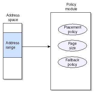
Any portion of a virtual address space, down to the level of a page, may be connected to a specific policy using a policy module. A policy module is simply an instantiation of a policy, as shown in Figure 1-1.
A policy module (PM) contains the policy methods used to handle each of the operations shown in Table 1-1.
Table 1-1. Virtual Memory Operations with Selectable Policy
Operation | Policy | Description |
|---|---|---|
Initial memory allocation | Placement policy | Determines what physical memory node to use when memory is allocated. |
| Page size policy | Determines what virtual page size to use to map physical memory. |
| Fallback policy | Determines the relative importance between placement and page size. |
| Migration policy | Not used. |
| Replication policy | Not used. |
| Paging policy | Not used. |
When the operating system needs to execute an operation to manage a section of an address space of a process, it uses the methods provided by memory policies. The memory policies are specified by the policy module connected (attached) to that virtual address space section.
To allocate a physical page, the first action of the virtual memory system's physical memory allocator is to call the method provided by the placement policy that determines from where the page should be allocated. Internally, this method returns a handle identifying the node memory from which the page should be allocated. Some of the selectable placement policies are as follows:
First touch. The page comes from the node where the allocation is taking place.
Fixed. The page comes from some predetermined node or set of nodes
Round-robin. The source node is selected from a predetermined set of nodes following a round-robin algorithm.
The second action of the physical memory allocator is to determine the page size to be used for the current allocation. This page size is acquired using a method provided by the page-size policy. Using the source node and the page size information, the physical memory allocator calls a per-node memory allocator specifying both parameters. If the system finds memory on this node that meets the page size requirement, the allocation operation finishes successfully; if not, the operation fails, and a fall back method from the fall back policy is called. The fall back method provided by this policy determines whether to try the same page size on a different node, a smaller page size on the same source node, sleep, or just fail.
The fall back policy to use depends on the kind of memory access patterns an application exhibits. If the application tends to generate many cache misses, giving locality precedence over the page size may be necessary; otherwise, in the situation where the application's working set is large, but has reasonable cache behavior, giving the page size higher precedence may be more efficient.
Once a page has been placed, it stays on its source node until it is either migrated to a different node, or paged out and faulted back in. Migration of a page to a different node can be performed explicitly by the user application or during a dynamic cpuset move.
This section describes how to create a policy module and covers the following topics:
A policy module can be created using the following memory management control interface call:
#include <sys/pmo.h>
typedef struct policy_set {
        char*  placement_policy_name;
        void*  placement_policy_args;
        char*  fallback_policy_name;
        void*  fallback_policy_args;
        char*  replication_policy_name;
        void*  replication_policy_args;
        char*  migration_policy_name;
        void*  migration_policy_args;
        char*  paging_policy_name;
        void*  paging_policy_args;
        size_t page_size;
} policy_set_t;

pmo_handle_t pm_create(policy_set_t* policy_set); |
The policy_set_t structure contains all the data required to create a policy memory module. For each selectable policy listed in Table 1-1, this structure contains a field to specify the name of the selected policy and the list of possible arguments that the selected policy may require. The page size policy is the exception, for which the specification of the wanted page size suffices. For example:
policy_set.placement_policy_name = "PlacementFixed";
        policy_set.placement_policy_args = NULL;
        policy_set.recovery_policy_name = "RecoveryDefault";
        policy_set.recovery_policy_args = NULL;
        policy_set.replication_policy_name = "ReplicationDefault";
        policy_set.replication_policy_args = NULL;
        policy_set.migration_policy_name = "MigrationDefault";
        policy_set.migration_policy_args = NULL;
        policy_set.paging_policy_name = "PagingDefault";
        policy_set.paging_policy_args = NULL;
policy_set.page_size = PM_PAGESZ_DEFAULT; |
This example shows populating the policy_set_t structure with policy arguments to create a policy module with a placement policy called PlacementFixed that takes no arguments. All other policies are set to be the default policies, including the page size.
Since populating this structure with mostly default values is a common operation, the IRIX operating system provides a special call to pre-fill this structure with default values as follows:
void pm_filldefault(policy_set_t* policy_set); |
The pm_create call returns a handle to the policy module just created, or a negative long integer in case of error, in which case errno is set to the corresponding error code.
The handle returned by the pm_create function is of the type pmo_handle_t. The policy management object (PMO) is a type common for all handles returned by all the memory management control interface calls. These handles are used to identify the different memory control objects created for an address space, much in the same way as file descriptors are used to identify open files or devices. Every address space contains one independent PMO table. A new table is created only when a process issues an exec call.
A simpler way to create a policy module is to use the restricted policy module creation call (pm_create) as follows:
pmo_handle_t pm_create_simple(char* plac_name,
                                     void* plac_args,
                                     char* repl_name,
                                     void* repl_args,
size_t page_size); |
This call allows for the specification of only the placement policy, the replication policy, and the page size. Defaults are automatically chosen for the fall back policy, the migration policy, and the paging policy.
The current list of available policies is shown in Table 1-2.
Table 1-2. Available Policy Types
Policy Type | Policy Name | Arguments |
|---|---|---|
Placement policy | PlacementDefault | No arguments |
| PlacementFixed | Memory locality domain |
| PlacementFirstTouch | No arguments |
| PlacementRoundRobin | Round robin Mldset |
| PlacementThreadLocal | Application Mldse |
Fall back policy | FallbackDefault | No arguments |
| FallbackLargepage | No arguments |
| FallbackLocal | No arguments |
Replication policy | ReplicationDefault | No arguments |
| ReplicationOne | No arguments |
Migration policy | MigrationDefault | No arguments |
| MigrationControl | Migration parameters ( migr_policy_uparms_t) |
Paging policy | PagingDefault | No arguments |
The memory management control interface (MMCI) allows you to select different policies for different sections of a virtual address space at the page level of granularity. To associate a virtual address space section with a set of policies, you need to first create a policy module with the wanted policies, as described in the “Available Policies”, and then use the following MMCI call:
int pm_attach(pmo_handle_t pm_handle, void* base_addr, size_t length); |
The pm_handle call identifies the policy module you previously created; base_addr is the base virtual address of the virtual address space section you want to associate to the set of policies; and length is the length of the section.
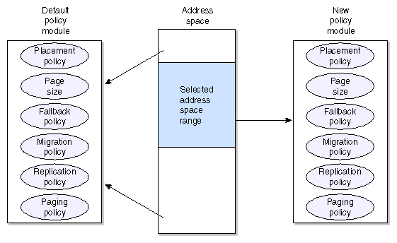
After creating a policy module, and attaching a section of the virtual address space of a process to this new policy module, you end up with the scenario depicted in Figure 1-2.
A new default policy module is created and inserted in the PMO name space every time a process issues an exec call. This default policy module is used to define memory management policies for all freshly created memory regions. This default policy module can later be overridden by users using the pm_attach MMCI call.
This default policy module is created with the following policies:
PlacementDefault
FallbackDefault
ReplicationDefault
MigrationDefault
PagingDefault
16-KB Pages
The default policy module is used in the following situations:
At exec time, when IRIX creates the basic memory regions for the stack, text, and heap
At fork time, when IRIX creates all the private memory regions
At sproc time, when IRIX creates all the private memory regions (at least the stack when the complete address space is shared)
When memory mapping a file or a device
When growing the stack and IRIX finds that the stack's region has been removed by the user using unmap, or you have done a setcontext, moving the stack to a new location
When using an sbreak call and IRIX finds that the user has removed the associated region using munmap, or the region was not growable, anonymous, or copy-on-write
When a process attaches a portion of the address space of a “monitored” process via procfs, and a new region needs to be created
When you attach an System V shared memory region
The default policy module is also stored in the per-process group PMO name space, and therefore follows the same inheritance rules as all policy modules. It is inherited at fork or sproc time, and a new one is created at exec time. For more information, see “Name Spaces for Memory Management Control”.
You can select a new default policy module for the stack, text, and heap as follows:
pmo_handle_t pm_setdefault(pmo_handle_t pm_handle, mem_type_t mem_type); |
The pm_handle argument is the handle returned by pm_create. The mem_type argument is used to identify the memory section for which you want to change the default policy module and it can take any of the following values:
MEM_STACK
MEM_STACK
MEM_DATA
You can also obtain a handle to the default policy module using the following call:
pmo_handle_t pm_getdefault(mem_type_t mem_type); |
This call returns a PMO handle referring to the address space of the calling process default policy module for the specified memory type. The handle is greater or equal to zero when the call succeeds, and it's less than zero when the call fails, and errno is set to the appropriate error code.
Policy modules are automatically destroyed when all the members of a process group or a shared group have died. However, you can explicitly ask the operating system to destroy policy modules that are not in use anymore, using the following call:
int pm_destroy(pmo_handle_t pm_handle); |
The pm_handle argument is the handle returned by pm_create.
Any association to this policy module that already exists will remain effective, and the policy module will only be destroyed when the section of the address space that is associated with this policy module is also destroyed (unmapped), or when the association is overridden using a pm_attach call.
You can obtain the list of policy modules currently associated with a section of a virtual address space by using the following call:
typedef struct pmo_handle_list {
        pmo_handle_t* handles;
        uint          length;
} pmo_handle_list_t;
int pm_getall(void* base_addr,
size_t length,
pmo_handle_list_t* pmo_handle_list); |
The base_addr argument is the base address for the section that you are inquiring about; length is the length of the section, and pmo_handle_list is a pointer to a list of handles as defined by the structure pmo_handle_list_t .
On success, this call returns the effective number of policy modules that are being used by the specified virtual address space range. If this number is greater than the size of the list to be used as a container for the policy module handles, you can infer that the specified virtual address space range is using more policy modules than can fit on the list.
On failure, this call returns a negative integer, and errno is set to the corresponding error code.
Users also have read-only access to the internal details of a policy module, using the following call:
char placement_policy_name[PM_NAME_SIZE + 1]; char fallback_policy_name[PM_NAME_SIZE + 1]; char replication_policy_name[PM_NAME_SIZE + 1]; char migration_policy_name[PM_NAME_SIZE + 1]; char paging_policy_name[PM_NAME_SIZE + 1]; size_t page_size; int policy_flags; pmo_handle_t pmo_handle; } pm_stat_t; int pm_getstate(pmo_handle_t pm_handle, pm_stat_t* pm_stat); |
The pm_handle argument identifies the policy modules about which the user needs information, and pm_stat is an output parameter of the form defined by the structure pm_stat_t.
On success, this call returns a nonnegative integer and the policy module internal data in pm_stat. On error, the call returns a negative integer and errno is set to the corresponding error code.
You can modify the page size of a policy module by using the following memory management control interface (MMCI) call:
int pm_setpagesize(pmo_handle_t pm_handle, size_t page_size); |
The pm_handle argument identifies the policy module for which you are changing page size. The page_size argument is the requested page size.
On success, this call returns a nonnegative integer. On error, it returns a negative integer with errno set to the corresponding error code.
One of the most important goals of memory management in a ccNUMA system like the SGI 2000 or a NUMAflex system like the SGI Orgin 3000 series of systems is the maximization of locality.
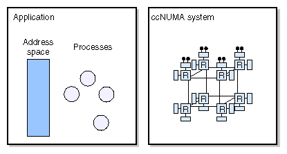
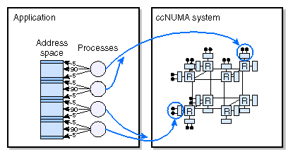
The scenario presented in Figure 1-3 shows a shared memory application using 4 processes that you want to run on an SGI 2000 system.
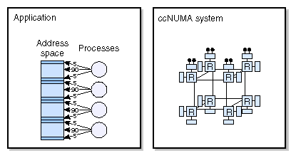
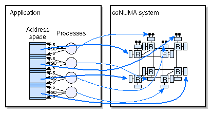
Figure 1-4, shows the kind of memory access patterns produced by this application. The memory accesses issued by each process produce 90% of the cache misses of a process to a an almost unshared section of memory, 5% to a section of memory shared with another process, and another 5% to a section of memory shared with a third process.
If you do not pay attention to locality, you may end up with memory and processors mapped to hardware, as shown in Figure 1-5. A couple of processes may end up running on one corner of the machine and the other processes may end up running in the exact opposite corner, causing the memory section shared by the second and third process to present very long latencies for one of the pairs.
And it turns out, this is not all that bad in that you could potentially end up with each process running on different distant nodes and memory mapped on another set of completely different distant nodes. This chaotic mapping is shown in Figure 1-6.
The IRIX operating system uses several mechanisms to manage locality and avoid the scenarios preceding:
It schedules memory in such a way that applications can allocate large amounts of relatively close memory pages.
It performs topology-aware initial memory placement.
It provides a topology-aware process scheduler fully cognizant of the memory affinity exhibited by processes.
It allows and encourages application writes to provide initial placement hints, using high level tools, environment variables, or direct system calls.
It allows users to select different policies for the most important memory management operations.
The following sections of this manual describe each one of these items.
The placement policy defines the algorithm used by the physical memory allocator to decide what memory source to use to allocate a page in a multinode ccNUMA or NUMAflex machine. The goal of this algorithm is to place memory in such a way that local accesses are maximized.
The optimal placement algorithm would have pre-knowledge of the exact number of cache misses triggered by each thread sharing the page it is about to place. Using this knowledge, the algorithm would place the page on the node where the thread generating the most cache misses is running, assuming that thread always runs on the same node.
Unfortunately, the placement algorithm does not have perfect previous knowledge. The algorithm has to be based on heuristics that predict the memory access patterns and cache misses on a page or on user provided hints.
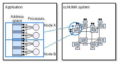
For example, Figure 1-7 shows a placement policy that maximizes access. Two processes are executed on the 2 CPUs in a node, the other 2 processes are executed on the CPUs of adjacent nodes; and memory for the first pair of processes is allocated from the first node, and memory for the second pair of processes is allocated from the second node.
All placement policies are based on two abstractions of physical memory nodes:
Memory locality domains (MLDs)
Memory locality domain sets (MLD sets)
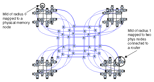
An MLD with center c and radius r is a source of physical memory composed of all memory nodes within a “hop distance” r of a center node c.
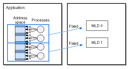
Figure 1-8, shows two MLDs. The left MLD has a radius of 0, meaning that no network hops are needed in order to access memory from a processor attached to its center node. The right MLD has a radius of 1, indicating that at most one network hop is needed to access memory from a processor attached to its center node.
MLDs may be interpreted as virtual memory nodes. Normally, the application writer defining MLDs specifies the MLD radius, and lets the operating system decide where it will be centered. The operating system tries to choose a center according to current memory availability and other placement parameters that the user may have specified such as device affinity and topology.
You can create MLDs using the following MMCI call:
pmo_handle_t mld_create(int radius, long size); |
The radius argument defines the MLD radius and the argument size is a hint specifying approximately how much physical memory will be required for this MLD.
On success, this call returns a handle for the newly created MLD. On failure, this call returns a negative long integer and errno is set to the corresponding error code.
MLDs are not placed when they are created. The MLD handle returned by the constructor cannot be used until the MLD has been placed by making it part of an MLDSET.
For this example application, you would create two MLDs as shown in Figure 1-9.
You can also destroy MLDs that are no longer being used with the following call:
int mld_destroy(pmo_handle_t mld_handle); |
The argument mld_handle is the handle returned by the mld_create function. On success, this call returns a non-negative integer. On failure, it returns a negative integer and errno is set to the corresponding error code.
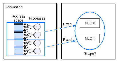
Memory locality domain sets (MLD sets) address the issue of placement topology and device affinity. For this example application, you could create two MLDs, but if no topological information is specified, the system would be free to place them anywhere (see Figure 1-10). You want the two MLDs to be placed as close as possible.
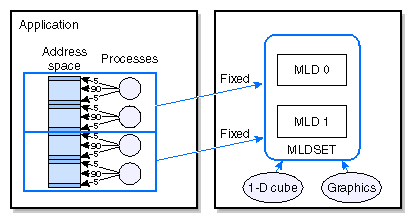
An MLDSET is a group of MLDs with an associated topology and device (resource, in general) affinity, as shown in Figure 1-11.
You can create MLDSETs using the following MMCI call:
pmo_handle_t mldset_create(pmo_handle_t* mldlist, int mldlist_len); |
The mldlist argument is an array of MLD handles containing all the MLDs you want to make part of the new MLDSET, and the mldlist_len argument is the number of MLD handles in the array.
On success, this call returns an MLDSET handle. On failure, this call returns a negative long integer and errno is set to the corresponding error code.
This call creates only a basic MLDSET without any placement information. An MLDSET in this state is useful just to specify groups of MLDs that have already been placed. In order to have the operating system place this MLDSET, and therefore place all the MLDs that are now members of this MLDSET, you have to specify the desired MLDSET topology and device affinity, using the following MMCI call:
int mldset_place(pmo_handle_t mldset_handle, topology_type_t topology_type, raff_info_t* rafflist, int rafflist_len, rqmode_t rqmode); |
The mldset_handle argument is the MLDSET handle returned by the mldset_create function and it identifies the MLDSET that the user is placing. The topology_type argument specifies the topology the operating system should consider in order to place this MLDSET, which can be one of the following:
TOPOLOGY_FREE
This topology specification allows the operating system to determine what shape to use to allocate the set. The operating system tries to place this MLDSET on a cluster of physical nodes as compact as possible, depending on the current system load
TOPOLOGY_CUBE
This topology specification is used to request a cube-like shape.
TOPOLOGY_CUBE_FIXED
This topology specification is used to request a perfect cube.
TOPOLOGY_PHYSNODES
This topology specification is used to request that the MLDs in an MLDSET be placed in the exact physical nodes enumerated in the device affinity list, described in the following topology_type_t type:
/*
 * Topology types for mldsets
 */
typedef enum {
        TOPOLOGY_FREE,
        TOPOLOGY_CUBE,
        TOPOLOGY_CUBE_FIXED,
        TOPOLOGY_PHYSNODES,
        TOPOLOGY_LAST
} topology_type_t;
The rafflist argument is used to specify resource affinity. It is an array of resource specifications using the structure shown below:
/*
 * Specification of resource affinity.
 * The resource is specified via a
 * file system name (dev, file, etc).
*/
typedef struct raff_info {
	void* resource;
ushort reslen;
ushort restype;
ushort radius;
ushort attr;
} raff_info_t; |
The resource, reslen, and restype fields define the resource. The resource field is used to specify the name of the resource, the reslen field must always be set to the actual number of bytes to which the resource pointer points, and the restype field specifies the kind of resource identification being used, which can be any of the following:
RAFFIDT_NAME
This resource identification type should be used for the cases where a hardware graph pathname is used to identify the device.
RAFFIDT_FD
This resource identification type should be used for the cases where a file descriptor is being used to identify the device.
The radius field defines the maximum distance from the actual resource where you want the MLDSET to be placed. The attr field specifies whether you want the MLDSET to be placed closed or far from the resource:
RAFFATTR_ATTRACTION
The MLDSET should be placed as close as possible to the specified device.
RAFFATTR_REPULSION
The MLDSET should be placed as far as possible from the specified device.
The rafflist_len argument in the mldset_place call specifies the number of raff structures the process is passing via rafflist.
Finally, the rqmode argument is used to specify whether the placement request is ADVISORY or MANDATORY:
/*
 * Request types
 */
typedef enum {
        RQMODE_ADVISORY,
        RQMODE_MANDATORY
} rqmode_t; |
On success, the mldset_place call returns a nonnegative integer on success. On failure, it returns a negative integer and errno is set to the corresponding error code.
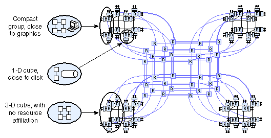
The IRIX operating system places the MLDSET by finding a section of the machine that meets the requirements of topology, device affinity, and expected physical memory used, as shown in Figure 1-12.
Users can destroy MLDSETs using the following call:
int mldset_destroy(pmo_handle_t mldset_handle); |
The mldset_handle argument identifies the MLDSET to be destroyed.
On success, this call returns a nonnegative integer. On failure, it returns a negative integer and errno is set to the corresponding error code.
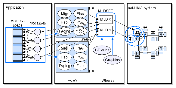
After creating MLDs and placing them using an MLDSET, you can create a policy module that makes use of these memory sources and attach sections of a virtual address space to this policy module, as shown in Figure 1-13.
You still need to make sure that the application threads will be executed on the nodes where you are allocating memory. To ensure this, you need to link threads to MLDs using the following call:
int process_mldlink(pid_t pid, pmo_handle_t mld_handle); |
The pid argument is the process ID of the process to be linked to the MLD specified by the mld_handle argument. On success, this call return a nonnegative integer. On failure, it returns a negative integer and errno is set to the corresponding error code.
After using this call on the example application, linking the first two processes to MLD0 and the last two processes to MLD1, you end up with the scenario shown in Figure 1-14.
The memory management control module uses two name spaces as follows:
Policy name space
This is a global system name space that contains all the policies that have been exported and therefore are available to users. The domain of this name space is the set of exported policy names, strings of characters such as PlacementDefault, and its range is the corresponding set of policy constructors.
Internally, the operating system searches for each name in the policy name space thereby obtaining the constructors for each of the specified policies, which are used to initialize the actual internal policy module object.
Policy management object name space
This is a per-process group, either shared (sproc processes) or not shared (fork processes), name space used to store handles for all the policy management objects that have been created within the context of any of the members of the process group.
The domain of this name space is the set of policy management object (PMO) handles and its range is the set of references (internal kernel pointers) to the PMOs.
PMO handles can refer to any of several kinds of policy management objects:
Policy modules
Memory locality domains (MLDs)
Memory locality domain sets (MLDSETs
The PMO name space is inherited at fork or sproc time and is created at exec time.
